- 您現在的位置:買賣IC網 > PDF目錄30722 > LA7383 SPECIALTY CONSUMER CIRCUIT, PDIP36 PDF資料下載
參數資料
| 型號: | LA7383 |
| 元件分類: | 消費家電 |
| 英文描述: | SPECIALTY CONSUMER CIRCUIT, PDIP36 |
| 封裝: | SDIP-36 |
| 文件頁數: | 7/13頁 |
| 文件大小: | 184K |
| 代理商: | LA7383 |
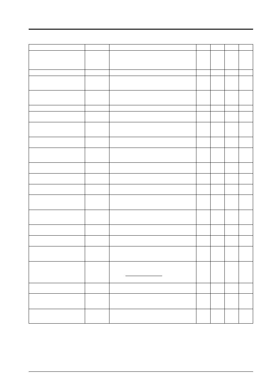
Continued from preceding page.
Parameter
Symbol
Conditions
min
typ
max
Unit
White insertion level (REC)
WHR
Measure T28 DC voltage when 1.3 V is applied to
T27, and assign the measured value to LWHR
and calculate the difference with LWHI
WHR =LWHI –LWHR
40
140
240
mV
VCA detection voltage
VVCA
Measure T8 DC voltage
2.80
2.95
3.10
V
Comb filter adjustment
VIN = standard multiburst signal 1 Vp-p and S30
= off, adjust so that the 3.58 MHz component at
T21 is at a minimum
Y-comb characteristics
GY-Comb
Measure the chroma level at T2 with a spectrum
analyzer, VIN = standard chroma noise test signal
1 Vp-p and S30 = off
–25
dB
C-comb characteristics
GC-Comb
VIN = white 50% + CW 3.0 MHz
–25
dB
REC YNR operation
EP/LP (1)
VR-YNR1
Measure the YNR addition level at T2 with VIN =
standard color bar signal 1 Vp-p and S30 = off
10
12
14
mV
REC YNR operation
EP/LP (2)
VR-YNR2
Measure the YNR addition level at edit mode T2
with VIN = standard color bar signal 1 Vp-p and
S30=off
234
mV
Pre-CCD LPF
frequency characteristics (1)
GPFIL1
Input a standard multiburst signal (1 Vp-p) and
measure the 4 MHz response for 500 kHz at T11
–0.5
0
+0.5
dB
Pre-CCD LPF
frequency characteristics (2)
GPFIL2
10 MHz response for 500 kHz at T11 when
VIN = standard multiburst signal 1 Vp-p and
S30=off
–10
–8
–6
dB
3MLPF
frequency characteristics (1)
G3MLP1
1 MHz response for 500 kHz at T2 when VIN =
standard multiburst signal 1 Vp-p and S30 = off
–0.5
0
+0.5
dB
3MLPF
frequency characteristics (2)
G3MLP2
2 MHz response for 500 kHz at T2 when VIN =
standard multiburst signal 1 Vp-p and S30 = off
–1
0
+1
dB
3MLPF
frequency characteristics (3)
G3MLP3
3 MHz response for 500 kHz at T2 when VIN =
standard multiburst signal 1 Vp-p and S30 = off
–10
–8
–6
dB
3MLPF
frequency characteristics (4)
G3MLP4
3.58 MHz response for 500 kHz at T2 when
VIN = standard multiburst signal 1 Vp-p and
S30=off
–30
dB
3MLPF
frequency characteristics (5)
G3MLP5
4.2 MHz response for 500 kHz at T2 when
VIN = standard multiburst signal 1 Vp-p and
S30=off
–15
dB
FM modulator output level
VFM
No input, use VR36 to adjust output frequency to
4 MHz, measure output level
0.8
1.0
1.2
Vp-p
FM modulator
secondary distortion
HMOD
Ratio of 8 MHz component to 4 MHz in the above
state
–40
–35
dB
FM modulator
modulation sensitivity
SMOD
Measure amplitude of change in output frequency
when 2.6 V DC or 3.1 V DC is applied to T3,
2 x (f3.1 – f2.6)
1.6
2.0
2.4
MHz/V
FM modulator linearity
LMOD
Measure output frequency when 2.85 V DC
applied to T3, f2.85
LMOD =
f2.85 – (f3.1 + f2.6)/2
f3.1 – f2.6
x 100
–3
0
+2
%
1/2 fH carrier shift 1
CS1
Measure amplitude of change in output frequency
when SW35B is from on to off and SW35A is off
6.8
7.8
9.5
kHz
1/2 fH carrier shift 2
CS2
Measure amplitude of change in output frequency
when SW35A is on and SW35B is switch from on
to off
6.8
7.8
9.5
kHz
Emphasis gain
GEMP
VIN = 0.5 mVp-p 10 kHz sine wave
Measure ratio of levels of input and output
amplitude at T4
–0.5
0
+0.5
dB
Continued on next page.
LA7383
No.4032-3/13
相關PDF資料 |
PDF描述 |
|---|---|
| LA7386 | SPECIALTY CONSUMER CIRCUIT, PDIP36 |
| LA7391AN | SPECIALTY CONSUMER CIRCUIT, PDIP42 |
| LA7411M | 2 CHANNEL, VIDEO PREAMPLIFIER, PDSO24 |
| LA7411 | 2 CHANNEL, VIDEO PREAMPLIFIER, PDIP24 |
| LA7415 | 4 CHANNEL, VIDEO AMPLIFIER, PDIP30 |
相關代理商/技術參數 |
參數描述 |
|---|---|
| LA7386 | 制造商:SANYO 制造商全稱:Sanyo Semicon Device 功能描述:NTSC Video Signal Processing LSI for VCRs |
| LA7390 | 制造商:SANYO 制造商全稱:Sanyo Semicon Device 功能描述:VHS-format VCR Video Signal Processor |
| LA7390L | 制造商:未知廠家 制造商全稱:未知廠家 功能描述:VHS-format VCR Video Signal Processor(295.40 k) |
| LA7390N | 制造商:SANYO 制造商全稱:Sanyo Semicon Device 功能描述:VHS-format VCR Video Signal Processor |
| LA7391 | 制造商:未知廠家 制造商全稱:未知廠家 功能描述: |
發布緊急采購,3分鐘左右您將得到回復。