- 您現在的位置:買賣IC網 > PDF目錄30725 > LA76810HA AM/FM, AUDIO/VIDEO DEMODULATOR, PDIP54 PDF資料下載
參數資料
| 型號: | LA76810HA |
| 元件分類: | 接收器 |
| 英文描述: | AM/FM, AUDIO/VIDEO DEMODULATOR, PDIP54 |
| 封裝: | 0.600 INCH, DIP-54 |
| 文件頁數: | 3/41頁 |
| 文件大小: | 417K |
| 代理商: | LA76810HA |
第1頁第2頁當前第3頁第4頁第5頁第6頁第7頁第8頁第9頁第10頁第11頁第12頁第13頁第14頁第15頁第16頁第17頁第18頁第19頁第20頁第21頁第22頁第23頁第24頁第25頁第26頁第27頁第28頁第29頁第30頁第31頁第32頁第33頁第34頁第35頁第36頁第37頁第38頁第39頁第40頁第41頁
LA76810HA
No.A1143-11/41
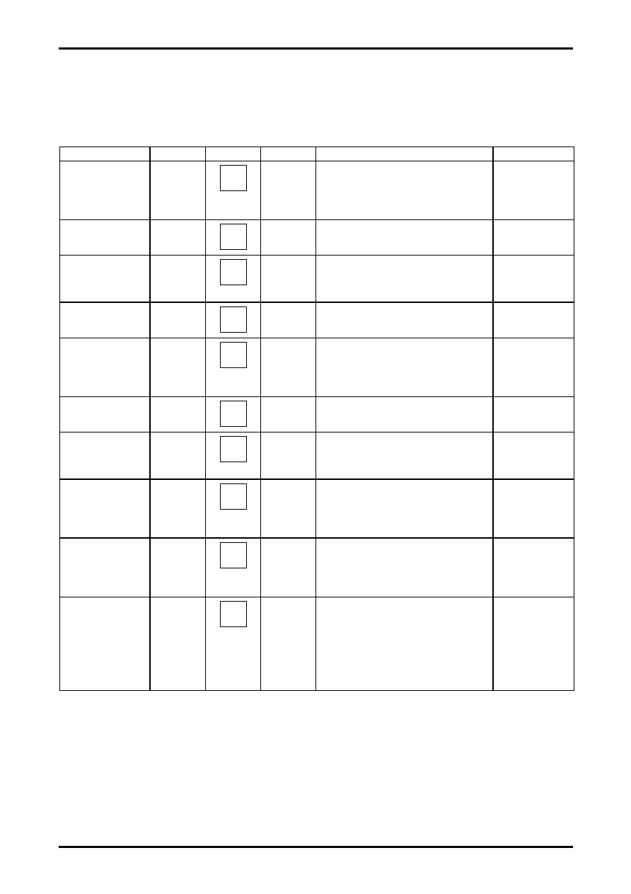
SIF Block (FM block) Input Signals and Test Conditions
Unless otherwise specified, the following conditions apply when each measurement is made.
1. Bus control condition: IF.AGC.SW = "1", SIF.SYS = "01", DEEM-TC = "0", FM.GAIN = "0"
2. SW:IF1 = "ON"
3. Input signals are input to pin 54 and the carrier frequency is 5.5MHz.
Input signal
Symbol
Test point
Input signal
Test method
Bus conditions
FM detection
output voltage
SOADJ
2
90dB
,
fm = 400Hz,
FM =
±30kHz
Adjust the DAC (FM.LEVEL) such that the 400Hz
component of the FM detection output at pin 2
become as close to 600mVrms as possible and
measure (SV1:mVrms) the output at that
moment.
FM limiting
sensitivity
SLS
2
fm = 400Hz,
FM =
±30kHz
Measure the input level (dB
) at which the 400Hz
component of the FM detection output at pin 2
becomes -3dB relative to SV1.
FM level =
Adjustment value
FM detection
output f characteristics
(fm = 100kHz)
SF
2
90dB
,
fm = 100kHz
FM =
±30kHz
Set SW: IF1 = "OFF".
Measure (SV2: mVrms) the FM detection output
of pin 2. Calculate as follows:
SF = 20*LOG (SV1/SV2) [dB]
FM level =
Adjustment value
FM detection output
distortion
STHD
2
90dB
,
fm = 400Hz,
FM =
±30kHz
Measure the distortion factor of the 400Hz
component of the FM detection output at pin 2.
FM level =
Adjustment value
AM rejection
ratio
SAMR
2
90dB
,
fm = 400Hz,
AM = 30%
Measure the 1kHz component (SV3: mVrms) of
the FM detection output at pin 2.
Assign the measured value to SV3 and
calculate as follows:
SAMR = 20*LOG (SV1/SV3) [dB]
FM level =
Adjustment value
SIF.S/N
SSN
2
90dB
,
CW
Measure the noise level (DIN AUDIO, SV4:
mVrms) at pin 2. Calculate as follows:
SSN=20*LOG(SV1/SV4) [dB]
FM level =
Adjustment value
PAL de-emph time
constant
SPTC
2
90dB
,
fm = 3.18KHz
FM =
±30KHz
Measure the 3.18kHz component (SV5: mVrms)
of the FM detection output at pin 2 and calculate
as follows:
SNTC = 20*LOG (SV1/SV5) [dB]
FM level =
Adjustment value
PAL/NT
Difference of voltage
gain
SGD
2
fo = 4.5MHz
90dB
,
fm = 400Hz
FM =
±15KHz
Measure the 400Hz component (SV6: mVrms) of
the FM detection output at pin 2 and calculate as
follows:
SNTC = 20*LOG (SV1/SV6) [dB]
FM level =
Adjustment value
SIF.SYS = "00"
DEEM-TC = "1"
FM.GAIN = "1"
NT de-emph
time constant
SNTC
2
fo = 4.5MHz
90dB
,
fm = 2.12kHz
FM =
±15kHz
Measure the 2.12kHz component (SV7: mVrms)
of the FM detection output at pin 2 and calculate
as follows:
SNTC = 20*LOG (SV6/SV7) [dB]
FM level =
Adjustment value
SIF.SYS = "00"
DEEM-TC = "1"
FM.GAIN = "1"
BPF 3db band width
SBW
2
90dB
,
CW
Set SW: IF1 = "OFF".
Pin9 = 5V
Measure the 458kHz component (SV8: mVrms)
at pin 2. Set the input frequency to 5.565MHz to
the input frequency and measure the 393kHz
component (SV9: mVrms) at pin 2 to calculate as
follows:
SBW = 20*LOG (SV8/SV9) [dB]
FM level=
Adjustment value
相關PDF資料 |
PDF描述 |
|---|---|
| LA76814 | HORIZ/VERT DEFLECTION IC, PDIP54 |
| LA76818A | AM/FM, AUDIO/VIDEO DEMODULATOR, PDIP54 |
| LA76818A | AM/FM, AUDIO/VIDEO DEMODULATOR, PDIP54 |
| LA76835NM | AM/FM, AUDIO/VIDEO DEMODULATOR, PQFP80 |
| LA76835NM | AM/FM, AUDIO/VIDEO DEMODULATOR, PQFP80 |
相關代理商/技術參數 |
參數描述 |
|---|---|
| LA76818A | 制造商:SANYO 制造商全稱:Sanyo Semicon Device 功能描述:The LA76818A is I2C bus controller ICs that support the different TV broadcast formats used worldwide and aim for rationalization of color TV set desi |
| LA76820 | 制造商:未知廠家 制造商全稱:未知廠家 功能描述:單片多制式TV處理集成電路 |
| LA76828N | 制造商:SANYO 制造商全稱:Sanyo Semicon Device 功能描述:電視小信號處理芯片 |
| LA76828N-A-E | 制造商:Sony Semiconductor Solutions Division 功能描述: |
| LA76832N | 制造商:SANYO 制造商全稱:Sanyo Semicon Device 功能描述:Monolithic Linear IC I2C Bus Control IC |
發布緊急采購,3分鐘左右您將得到回復。