- 您現在的位置:買賣IC網 > PDF目錄30733 > LC74782M ON-SCREEN DISPLAY IC, PDSO24 PDF資料下載
參數資料
| 型號: | LC74782M |
| 元件分類: | 畫面疊加 |
| 英文描述: | ON-SCREEN DISPLAY IC, PDSO24 |
| 封裝: | MFP-24 |
| 文件頁數: | 2/16頁 |
| 文件大小: | 183K |
| 代理商: | LC74782M |
Second byte
Note: The register states are all set to zero when the LC74782/M is reset with the RST pin.
{ COMMAND3 (Horizontal display start position and horizontal character size setup command)
First byte
Second byte
Note: The register states are all set to zero when the LC74782/M is reset with the RST pin.
No. 4989-10/16
LC74782, 74782M
Register content
DA0 to DA7
Register name
State
Function
Note
7
—
1
6
—
0
Command 3 identification code
5
—
1
Set the horizontal display start position and horizontal
4
—
1
character size.
3
HS21
0
1
Second line horizontal character size
2
HS20
0
1
HS11
0
1
First line horizontal character size
0
HS10
0
1
HS21
HS20
0
1
0
1 Tc per dot
2 Tc per dot
1
3 Tc per dot
1 Tc per dot
HS11
HS10
0
1
0
1 Tc per dot
2 Tc per dot
1
3 Tc per dot
1 Tc per dot
Register content
DA0 to DA7
Register name
State
Function
Note
7
—
0
Second byte identification bit
6
LC
0
An LC oscillator is used for the dot clock.
Selects the dot clock used in horizontal
1
A crystal oscillator is used for the dot clock.
character display.
5
HP5
0
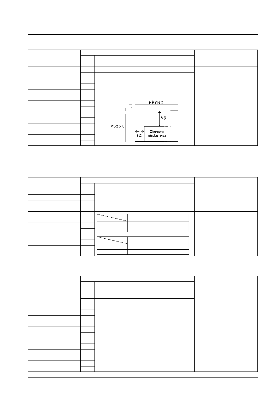
If HS is the horizontal start position then:
(MSB)
1
5
4
HP4
0
HS = Tc
× (2Σ 2nHP
n)
1
n = 0
3
HP3
0
1
2
HP2
0
1
HP1
0
1
0
HP0
0
(LSB)
1
The horizontal display start position is
set by the six bits HP5 to HP0.
The weight of bit 1 is 2Tc.
Tc: Period of the oscillator connected to OSCIN/OSCOUT in
operating mode.
Register content
DA0 to DA7
Register name
State
Function
Note
7
—
0
Second byte identification bit
6
FS
0
Crystal oscillator frequency: 2fsc
1
Crystal oscillator frequency: 4fsc
5
VP5
0
(MSB)
1
4
VP4
0
1
3
VP3
0
1
2
VP2
0
1
VP1
0
1
0
VP0
0
(LSB)
1
The vertical display start position is set
by the 6 bits VP0 to VP5.
The weight of bit 1 is 2H.
If VS is the vertical display start position then:
5
VS = H
× (2Σ 2nVP
n)
n = 0
H: the horizontal synchronization pulse period
相關PDF資料 |
PDF描述 |
|---|---|
| LC74782M | ON-SCREEN DISPLAY IC, PDSO24 |
| LC74783 | ON-SCREEN DISPLAY IC, PDIP24 |
| LC74783M | ON-SCREEN DISPLAY IC, PDSO24 |
| LC74783M | ON-SCREEN DISPLAY IC, PDSO24 |
| LC74783 | ON-SCREEN DISPLAY IC, PDIP24 |
相關代理商/技術參數 |
參數描述 |
|---|---|
| LC74782M-8A13-E | 制造商:ON Semiconductor 功能描述: |
| LC74782M-9011-E | 功能描述:顯示驅動器和控制器 RoHS:否 制造商:Panasonic Electronic Components 工作電源電壓:2.7 V to 5.5 V 最大工作溫度: 安裝風格:SMD/SMT 封裝 / 箱體:QFN-44 封裝:Reel |
| LC74783 | 制造商:SANYO 制造商全稱:Sanyo Semicon Device 功能描述:On-screen Display Controller LSI for VCR Products |
| LC74783M | 制造商:SANYO 制造商全稱:Sanyo Semicon Device 功能描述:On-screen Display Controller LSI for VCR Products |
| LC74783M-9014-E | 制造商:ON Semiconductor 功能描述:ON-SCREEN DISPLAY CONTROL - Ammo Pack |
發布緊急采購,3分鐘左右您將得到回復。