- 您現(xiàn)在的位置:買賣IC網(wǎng) > PDF目錄361024 > LM2599T-ADJ (NATIONAL SEMICONDUCTOR CORP) SIMPLE SWITCHER Power Converter 150 kHz 3A Step-Down Voltage Regulator, with Features PDF資料下載
參數(shù)資料
| 型號(hào): | LM2599T-ADJ |
| 廠商: | NATIONAL SEMICONDUCTOR CORP |
| 元件分類: | 穩(wěn)壓器 |
| 英文描述: | SIMPLE SWITCHER Power Converter 150 kHz 3A Step-Down Voltage Regulator, with Features |
| 中文描述: | 7.5 A SWITCHING REGULATOR, 173 kHz SWITCHING FREQ-MAX, PZFM7 |
| 封裝: | TO-220, 7 PIN |
| 文件頁數(shù): | 12/31頁 |
| 文件大小: | 812K |
| 代理商: | LM2599T-ADJ |
第1頁第2頁第3頁第4頁第5頁第6頁第7頁第8頁第9頁第10頁第11頁當(dāng)前第12頁第13頁第14頁第15頁第16頁第17頁第18頁第19頁第20頁第21頁第22頁第23頁第24頁第25頁第26頁第27頁第28頁第29頁第30頁第31頁
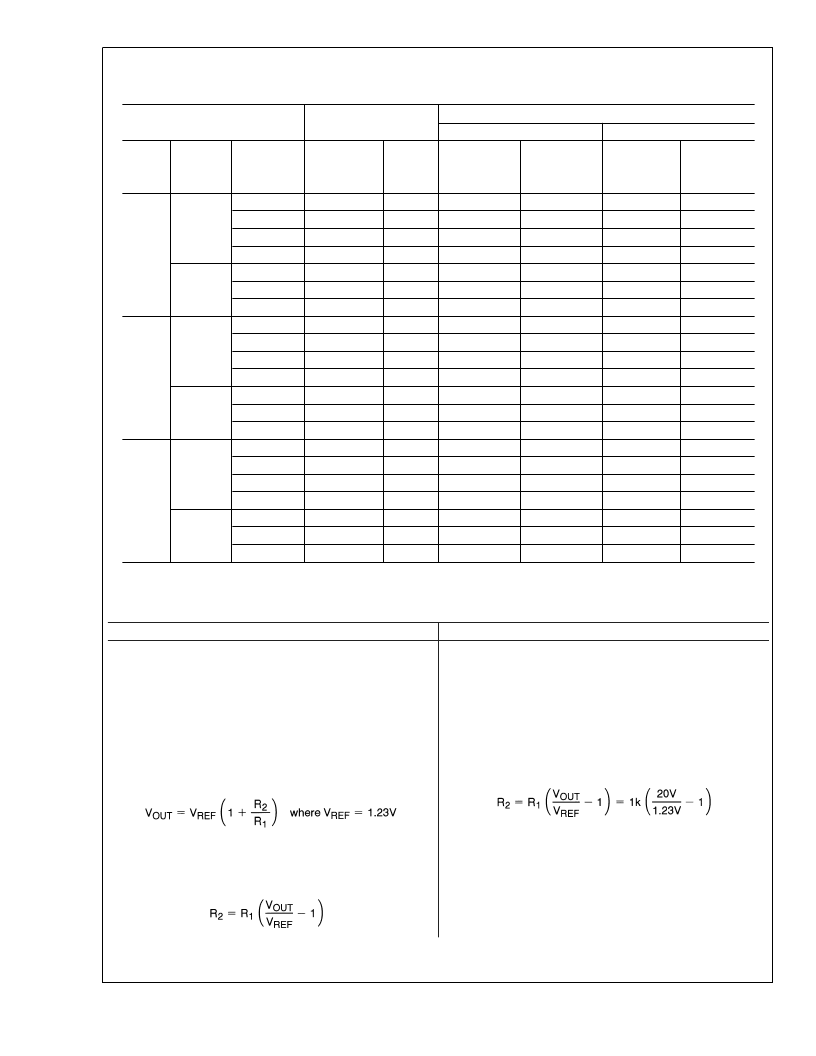
LM2599 Series Buck Regulator Design Procedure (Fixed Output)
(Continued)
LM2599 Series Buck Regulator Design Procedure (Adjustable Output)
PROCEDURE (Adjustable Output Voltage Version)
EXAMPLE (Adjustable Output Voltage Version)
Given:
V
OUT
= Regulated Output Voltage
V
IN
(max) = Maximum Input Voltage
I
LOAD
(max) = Maximum Load Current
F = Switching Frequency (Fixed at a nominal 150 kHz).
Given:
V
OUT
= 20V
V
IN
(max) = 28V
I
LOAD
(max) = 3A
F = Switching Frequency (Fixed at a nominal 150 kHz).
1. Programming Output Voltage
(Selecting R
1
and R
2
, as
shown in Figure 1)
Use the following formula to select the appropriate resistor
values.
Select a value for R
between 240
and 1.5 k
. The lower
resistor values minimize noise pickup in the sensitive feed-
back pin. (For the lowest temperature coefficient and the best
stability with time, use 1% metal film resistors.)
1. Programming Output Voltage
(Selecting R
1
and R
2
, as
shown in Figure 1)
Select R
1
to be 1 k
, 1%. Solve for R
2
.
R
2
= 1k (16.26 1) = 15.26k, closest 1% value is 15.4 k
.
R
2
= 15.4 k
.
Conditions
Inductor
Output Capacitor
Through Hole Electrolytic
Panasonic
HFQ Series
(μF/V)
470/25
560/35
680/35
560/35
470/25
330/35
330/35
470/25
560/25
330/35
330/35
470/25
180/35
180/35
470/25
330/25
180/25
180/35
330/25
180/25
82/25
Surface Mount Tantalum
AVX TPS
Series
(μF/V)
330/6.3
330/6.3
330/6.3
330/6.3
330/6.3
330/6.3
220/10
220/10
220/10
220/10
220/10
220/10
100/10
100/10
100/16
100/16
100/16
100/16
100/16
100/16
68/20
Output
Voltage
(V)
Load
Current
(A)
Max Input
Voltage
(V)
5
7
10
40
6
10
40
8
10
15
40
9
20
40
15
18
30
40
15
20
40
Inductance
(μH)
Inductor
(
#
)
Nichicon
PL Series
(μF/V)
560/16
560/35
680/35
470/35
470/35
330/35
270/50
560/16
560/25
330/35
270/35
560/16
180/35
180/35
470/25
330/25
180/25
180/35
330/25
180/25
82/25
Sprague
595D Series
(μF/V)
390/6.3
390/6.3
390/6.3
390/6.3
390/6.3
390/6.3
330/10
330/10
330/10
330/10
330/10
330/10
270/10
270/10
180/16
180/16
120/20
120/20
180/16
120/20
68/25
3.3
3
22
22
22
33
22
33
47
22
22
33
47
22
68
68
22
33
68
68
33
68
150
L41
L41
L41
L40
L33
L32
L39
L41
L41
L40
L39
L33
L38
L38
L41
L40
L44
L44
L32
L38
L42
2
5
3
2
12
3
2
FIGURE 2. LM2599 Fixed Voltage Quick Design Component Selection Table
L
www.national.com
12
相關(guān)PDF資料 |
PDF描述 |
|---|---|
| LM2619MTC | 500mA Step-Down DC-DC Converter |
| LM2619MTCX | 500mA Step-Down DC-DC Converter |
| LM2621MM | Low Input Voltage, Step-Up DC-DC Converter |
| LM2621 | |
| LM2622 | |
相關(guān)代理商/技術(shù)參數(shù) |
參數(shù)描述 |
|---|---|
| LM2599T-ADJ | 制造商:Texas Instruments 功能描述:SWITCHING REG 3A ADJ 2599 TO2207 |
| LM2599T-ADJ/NOPB | 功能描述:直流/直流開關(guān)轉(zhuǎn)換器 RoHS:否 制造商:STMicroelectronics 最大輸入電壓:4.5 V 開關(guān)頻率:1.5 MHz 輸出電壓:4.6 V 輸出電流:250 mA 輸出端數(shù)量:2 最大工作溫度:+ 85 C 安裝風(fēng)格:SMD/SMT |
| LM26 | 制造商:Psiber Data Systems 功能描述:LanMaster 26 Pro Link Tester and Accesory Kit |
| LM26_07 | 制造商:NSC 制造商全稱:National Semiconductor 功能描述:SOT-23, ±3°C Accurate, Factory Preset Thermostat |
| LM26001 | 制造商:NSC 制造商全稱:National Semiconductor 功能描述:1.5A Switching Regulator with High Efficiency Sleep Mode |
發(fā)布緊急采購,3分鐘左右您將得到回復(fù)。