- 您現在的位置:買賣IC網 > PDF目錄361028 > LM3916 (National Semiconductor Corporation) Dot/Bar Display Driver PDF資料下載
參數資料
| 型號: | LM3916 |
| 廠商: | National Semiconductor Corporation |
| 英文描述: | Dot/Bar Display Driver |
| 中文描述: | 點/酒吧顯示驅動程序 |
| 文件頁數: | 8/27頁 |
| 文件大小: | 509K |
| 代理商: | LM3916 |
第1頁第2頁第3頁第4頁第5頁第6頁第7頁當前第8頁第9頁第10頁第11頁第12頁第13頁第14頁第15頁第16頁第17頁第18頁第19頁第20頁第21頁第22頁第23頁第24頁第25頁第26頁第27頁
Mode Pin Functional Description
(Continued)
DOT OR BAR MODE SELECTION
The voltage at pin 9 is sensed by comparator C1, nominally
referenced to (V
+
100 mV). The chip is in bar mode when
pin 9 is above this level; otherwise it’s in dot mode. The com-
parator is designed so that pin 9 can be left open circuit for
dot mode.
Taking into account comparator gain and variation in the
100 mV reference level, pin 9 should be no more than 20 mV
below V
+
for bar mode and more than 200 mV below V
+
(or
open circuit) for dot mode. In most applications, pin 9 is ei-
ther open (dot mode) or tied to V
+
(bar mode). In bar mode,
pin 9 should be connected directly to pin 3. Large currents
drawn from the power supply (LED current, for example)
should not share this path so that large IR drops are avoided.
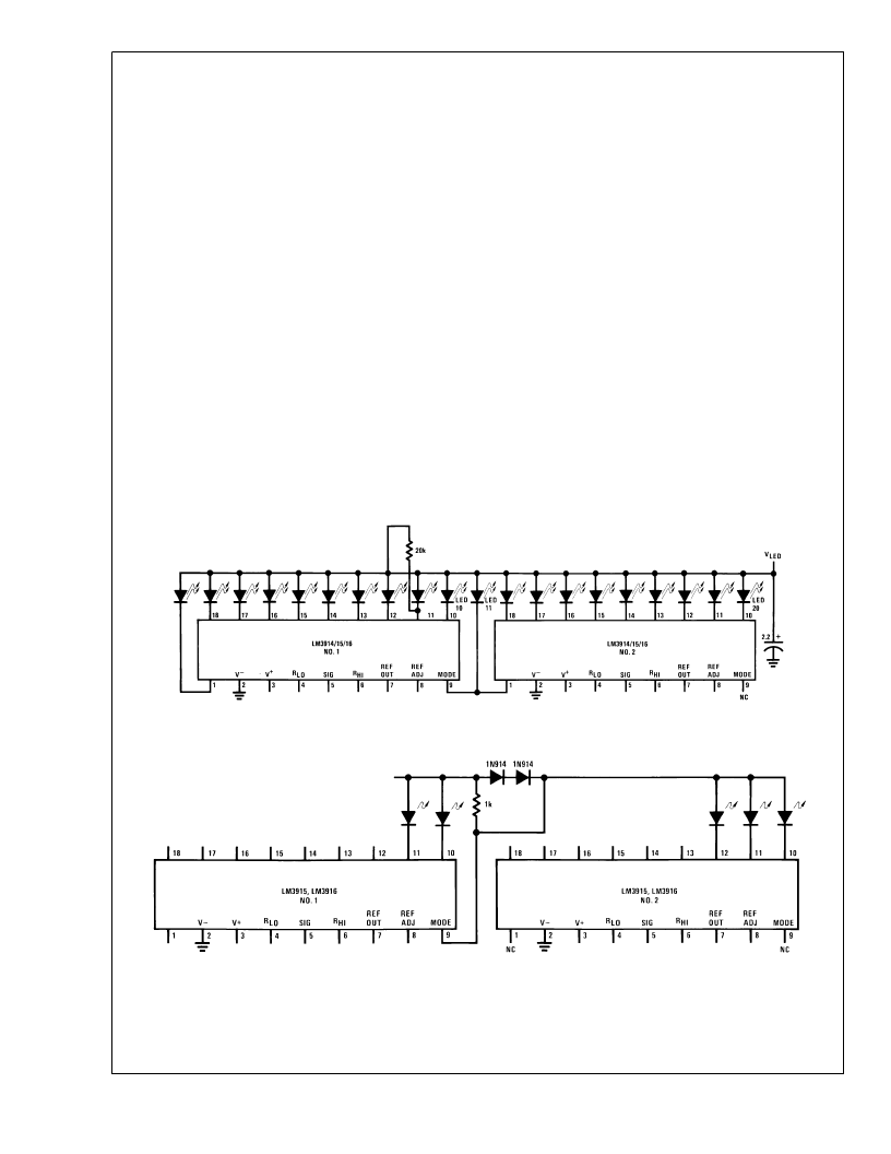
DOT MODE CARRY
In order for display to make sense when multiple drivers are
cascaded in dot mode, special circuitry has been included to
shut off LED
#
10 of the first device when LED
#
1 of the sec-
ond device comes on. The connection for cascading in dot
mode has already been described and is depicted in Figure
1
As long as the input signal voltage is below the threshold of
the second driver, LED
#
11 is off. Pin 9 of driver
#
1 thus sees
effectively an open circuit so the chip is in dot mode.As soon
as the input voltage reaches the threshold of LED
#
11, pin 9
of driver
#
1 is pulled an LED drop (1.5V or more) below
V
LED
. This condition is sensed by comparator C2, refer-
enced 600 mV below V
LED
. This forces the output of C2 low,
which shuts off output transistor Q2, extinguishing LED
#
10.
V
LED
is sensed via the 20k resistor connected to pin 11. The
very small current (less than 100 μA) that is diverted from
LED
#
9 does not noticeably affect its intensity.
An auxiliary current source at pin 1 keeps at least 100 μA
flowing through LED
#
11 even if the input voltage rises high
enough to extinguish the LED. This ensures that pin 9 of
driver
#
1 is held low enough to force LED
#
10 off when any
higher LED is illuminated. While 100 μA does not normally
produce significant LED illumination, it may be noticeable
when using high-efficiency LEDs in a dark environment. If
this is bothersome, the simple cure is to shunt LED
#
11 (and
LED
#
1) with a 10k resistor. The 1V 1R drop is more than the
900 mV worst case required to hold off LED
#
10 yet small
enough that LED
#
11 does not conduct significantly.
In some circuits a number of outputs on the higher device
are not used. Examples include the high resolution VU meter
and the expanded range VU meter circuits (see Typical Ap-
plications). To provide the proper carry sense voltage in dot
mode, the LEDs of the higher driver IC are tied to V
through two series-connected diodes as shown in Figure 2
Shunting the diodes with a 1k resistor provides a path for
driver leakage current.
DS007971-8
FIGURE 1. Cascading LM3914/15/16 Series in Dot Mode
DS007971-9
FIGURE 2. Cascading Drivers in Dot Mode with Pin 1 of Driver
#
2 Unused
L
www.national.com
8
相關PDF資料 |
PDF描述 |
|---|---|
| LM3916N | Dot/Bar Display Driver |
| LM3916N-1 | 6 PIN MINI DIN CABLE MM 50FT |
| LM395 | Ultra Reliable Power Transistors |
| LM395T | Ultra Reliable Power Transistors |
| LM399 | Precision Reference |
相關代理商/技術參數 |
參數描述 |
|---|---|
| LM3916J/A+ | 制造商:未知廠家 制造商全稱:未知廠家 功能描述:Vacuum Fluorescent Display Driver |
| LM3916N | 制造商:Texas Instruments 功能描述:IC DISPLAY DRIVER 3916 DIP18 制造商:Rochester Electronics LLC 功能描述: |
| LM3916N/A+ | 制造商:未知廠家 制造商全稱:未知廠家 功能描述:Vacuum Fluorescent Display Driver |
| LM3916N/B+ | 制造商:未知廠家 制造商全稱:未知廠家 功能描述:Vacuum Fluorescent Display Driver |
| LM3916N1 | 制造商:National Semiconductor 功能描述:LED DRVR 10Segment 3.3V/5V/9V/12V/15V/18V/24V 18-Pin PDIP Tube |
發(fā)布緊急采購,3分鐘左右您將得到回復。