- 您現在的位置:買賣IC網 > PDF目錄361034 > LM78S40 (National Semiconductor Corporation) RADIATION HARDENED HIGH EFFICIENCY, 5 AMP SWITCHING REGULATORS PDF資料下載
參數資料
| 型號: | LM78S40 |
| 廠商: | National Semiconductor Corporation |
| 元件分類: | 基準電壓源/電流源 |
| 英文描述: | RADIATION HARDENED HIGH EFFICIENCY, 5 AMP SWITCHING REGULATORS |
| 中文描述: | 抗輻射高效,5安培開關穩壓器 |
| 文件頁數: | 4/10頁 |
| 文件大小: | 289K |
| 代理商: | LM78S40 |
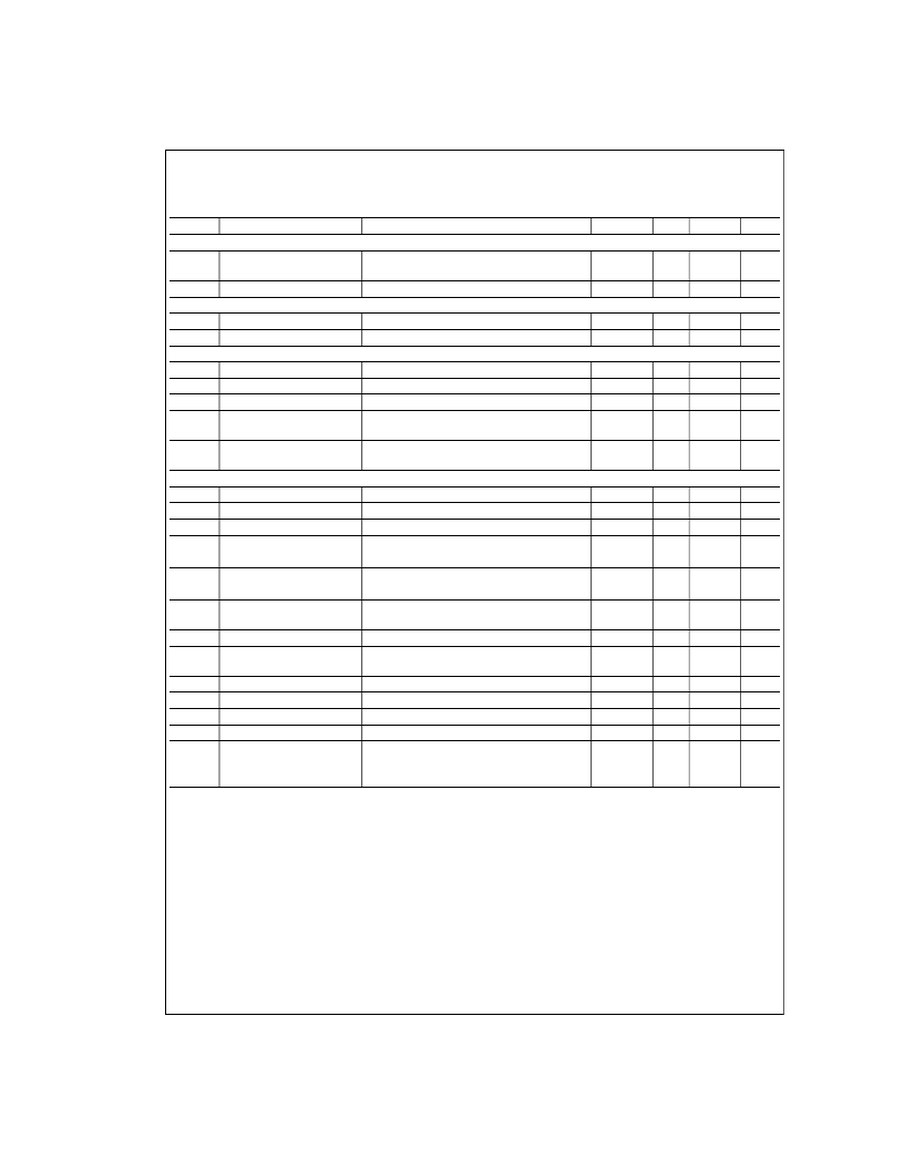
LM78S40
Electrical Characteristics
(Note 5) (Continued)
T
A
= Operating temperature range, V
IN
= 5.0V, V
+
(Op Amp) = 5.0V, unless otherwise specified.
Symbol
Parameter
OUTPUT SWITCH SECTION
h
FE
Output Transistor Current
Gain
I
L
Output Leakage Current
V
O
= 40V, T
A
= 25C
POWER DIODE
V
FD
Forward Voltage Drop
I
D
= 1.0A
I
DR
Diode Leakage Current
V
D
= 40V, T
A
= 25C
COMPARATOR
V
IO
Input Offset Voltage
V
CM
= V
REF
I
IB
Input Bias Current
V
CM
= V
REF
I
IO
Input Offset Current
V
CM
= V
REF
V
CM
Common Mode Voltage
Range
PSRR
Power Supply Rejection
Ratio
OPERATIONAL AMPLIFIER
V
IO
Input Offset Voltage
V
CM
= 2.5V
I
IB
Input Bias Current
V
CM
= 2.5V
I
IO
Input Offset Current
V
CM
= 2.5V
A
VS+
Voltage Gain
+
R
L
= 2.0 k
to GND;
V
O
= 1.0V to 2.5V, T
A
= 25C
A
VS
Voltage Gain
R
L
= 2.0 k
to V
+
(Op Amp)
V
O
= 1.0V to 2.5V, T
A
= 25C
V
CM
Common Mode Voltage
Range
CMR
Common Mode Rejection
V
CM
= 0V to 3.0V, T
A
= 25C
PSRR
Power Supply Rejection
Ratio
I
O+
Output Source Current
T
A
= 25C
I
O
Output Sink Current
T
A
= 25C
SR
Slew Rate
T
A
= 25C
V
OL
Output Voltage LOW
I
L
= 5.0 mA, T
A
= 25C
V
OH
Output Voltage High
I
L
= 50 mA, T
A
= 25C
Conditions
Min
Typ
Max
Units
I
C
= 1.0A, V
CE
= 5.0V, T
A
= 25C
70
10
nA
1.25
10
1.5
V
nA
1.5
35
5.0
15
200
75
V
IN
–2
mV
nA
nA
V
T
A
= 25C
0
V
IN
= 3.0V to 40V, T
A
= 25C
70
96
dB
4.0
30
5.0
250
15
200
75
mV
nA
nA
V/mV
25
25
250
V/mV
T
A
= 25C
0
V
CC
2
V
76
76
100
100
dB
dB
V
+
(Op Amp) = 3.0V to 40V, T
A
= 25C
75
10
150
35
0.6
mA
mA
V/μs
V
V
1.0
V + (Op
Amp)
3V
Note 1:
Absolute Maximum Ratings indicate limits beyond which damage to the device may occur. Electrical specifications do not apply when ordering the device
beyond its rated operating conditions.
Note 2:
T
J Max
= 150C for the Molded DIP, and 175C for the Ceramic DIP.
Note 3:
Ratings apply to ambient temperature at 25C. Above this temperature, derate the 16L-Ceramic DIP at 10 mW/C, and the 16L-Molded DIP at 8.3 mW/C.
Note 4:
For supply voltages less than 30V, the absolute maximum voltage is equal to the supply voltage.
Note 5:
A military RETS specification is available on request. At the time of printing, the LM78S40 RETS specification complied with the Min and Max limits in this
table. The LM78S40J may also be procured as a Standard Military Drawing.
www.national.com
4
相關PDF資料 |
PDF描述 |
|---|---|
| LM78 | Microprocessor System Hardware Monitor |
| LM78CCVF | Microprocessor System Hardware Monitor |
| LM78CCVF-J | Microprocessor System Hardware Monitor |
| LM79CCVF | Microprocessor System Hardware Monitor |
| LM79 | |
相關代理商/技術參數 |
參數描述 |
|---|---|
| LM78S40CN | 功能描述:直流/直流開關轉換器 RoHS:否 制造商:STMicroelectronics 最大輸入電壓:4.5 V 開關頻率:1.5 MHz 輸出電壓:4.6 V 輸出電流:250 mA 輸出端數量:2 最大工作溫度:+ 85 C 安裝風格:SMD/SMT |
| LM78S40CN | 制造商:Texas Instruments 功能描述:IC SWITCHING REGULATOR |
| LM78S40CN/NOPB | 功能描述:直流/直流開關轉換器 Uni Switching Reg Subsystem RoHS:否 制造商:STMicroelectronics 最大輸入電壓:4.5 V 開關頻率:1.5 MHz 輸出電壓:4.6 V 輸出電流:250 mA 輸出端數量:2 最大工作溫度:+ 85 C 安裝風格:SMD/SMT |
| LM78S40CN/NOPB | 制造商:Texas Instruments 功能描述:DC/DC Converter (DC-DC) / Switching Regu |
| LM78S40J | 制造商:Rochester Electronics LLC 功能描述:- Bulk |
發布緊急采購,3分鐘左右您將得到回復。