- 您現(xiàn)在的位置:買賣IC網(wǎng) > PDF目錄361039 > LMF90CMJ (NATIONAL SEMICONDUCTOR CORP) 4th-Order Elliptic Notch Filter PDF資料下載
參數(shù)資料
| 型號: | LMF90CMJ |
| 廠商: | NATIONAL SEMICONDUCTOR CORP |
| 元件分類: | 模擬濾波器 |
| 英文描述: | 4th-Order Elliptic Notch Filter |
| 中文描述: | SWITCHED CAPACITOR FILTER, ELLIPTIC, NOTCH, CDIP14 |
| 封裝: | 0.300 INCH, CERAMIC, DIP-14 |
| 文件頁數(shù): | 13/22頁 |
| 文件大小: | 411K |
| 代理商: | LMF90CMJ |
2.0 Applications Information
(Continued)
ALIASING
Another important characteristic of sampled-data systems is
their effect on signals at frequencies greater than one-half
the sampling frequency. (The LMF90’s sampling frequency
is the same as the filter’s clock frequency. This is the fre-
quency at the CLK pin). If a signal with a frequency greater
than one-half the sampling frequency is applied to the input
of a sampled-data system, it will be ‘‘reflected’’ to a frequen-
cy less than one-half the sampling frequency. Thus, an input
signal whose frequency is f
S
/2
a
10 Hz will cause the sys-
tem to respond as though the input frequency was f
s
/2
b
10 Hz. This phenomenon is known as ‘‘a(chǎn)liasing’’. Aliasing
can be reduced or eliminated by limiting the input signal
spectrum to less than f
s
/2.
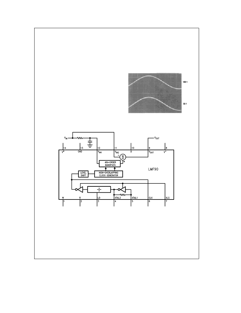
In some cases, it may be necessary to use a bandwidth
limiting filter (often a simple passive RC low-pass) ahead of
the bandpass input. Although the summing amplifier uses
switched-capacitor techniques, it does not exhibit aliasing
behavior, and the anti-aliasing filter need not be in its input
signal path. The filter can be placed ahead of pin 12 as
shown in Figure 4, with the non-band limited input signal
applied to pin 11. The output spectrum will therefore be
wideband, although limited by the bandwidth of the sum-
ming amplifier’s output buffer amplifier (typically 1 MHz),
even if f
CLK
is less than 1 MHz. Phase shift in the anti-alias-
ing filter will affect the accuracy of the notch transfer func-
tion, however, so it is best to use the highest available
clock-to-center-frequency ratio (100:1) and set the RC filter
cutoff frequency to about 15 to 20 times the notch frequen-
cy. This will provide reasonable attenuation of high-frequen-
cy input signals, while avoiding degradation of the overall
notch response. If the anti-aliasing filter’s cutoff frequency is
too low, it will introduce phase shift and gain errors large
enough to shift the frequency of the notch and reduce its
depth. A cutoff frequency that is too high may not provide
sufficient attenuation of unwanted high-frequency signals.
TL/H/10354–7
FIGURE 3. Output waveform of a switched-capacitor
filter. Note the voltage steps caused by sampling
at the clock frequency.
TL/H/10354–8
FIGURE 4. Using a simple passive low-pass filter to prevent aliasing in the presence of high-frequency input signals.
13
相關(guān)PDF資料 |
PDF描述 |
|---|---|
| LMF90CCWM | 4th-Order Elliptic Notch Filter |
| LMH6550 | Differential, High Speed Op Amp |
| LMH6550MA | Differential, High Speed Op Amp |
| LMH6550MAX | Differential, High Speed Op Amp |
| LMH6559 | High-Speed, Closed-Loop Buffer |
相關(guān)代理商/技術(shù)參數(shù) |
參數(shù)描述 |
|---|---|
| LMF90CMJ/883 | 制造商:NSC 制造商全稱:National Semiconductor 功能描述:4th-Order Elliptic Notch Filter |
| LM-FB20F-12 | 制造商:CML Innovative Technologies 功能描述:LED SRTIP FLEXIBLE 1X26 RGB |
| LM-FB26B | 制造商:CML Innovative Technologies 功能描述:LED STRIP FLEXIBLE 1X26 BLUE |
| LM-FB26B-12 | 制造商:CML Innovative Technologies 功能描述:LED STRIP FLEXIBLE 1X26 BLUE |
| LM-FB26G | 制造商:CML Innovative Technologies 功能描述:LED STRIP FLEXIBLE 1X26 GREEN |
發(fā)布緊急采購,3分鐘左右您將得到回復(fù)。