- 您現在的位置:買賣IC網 > PDF目錄361039 > LMH6559MF (NATIONAL SEMICONDUCTOR CORP) High-Speed, Closed-Loop Buffer PDF資料下載
參數資料
| 型號: | LMH6559MF |
| 廠商: | NATIONAL SEMICONDUCTOR CORP |
| 元件分類: | 緩沖放大器 |
| 英文描述: | High-Speed, Closed-Loop Buffer |
| 中文描述: | BUFFER AMPLIFIER, PDSO5 |
| 封裝: | SOT-23, 5 PIN |
| 文件頁數: | 16/22頁 |
| 文件大小: | 1078K |
| 代理商: | LMH6559MF |
Application Notes
(Continued)
this moment the voltage in the whole transmission line has
the nominal value of 2V (see
Figure 6
trace E). If the three
transmission lines each have a different length the particular
point in time at which the voltage at the series termination
resistor jumps to 2V is different for each case. However, this
transient is not transferred to the other lines because the
output of the buffer is low and this transient is highly attenu-
ated by the combination of the termination resistor and the
output impedance of the buffer. A simple calculation illus-
trates the point. Assume that the output impedance is 5
.
For the frequency of interest the attenuation is V
/V
= 55/5
= 11, where A and B are the points in
Figure 3
. In this case
the voltage caused by the reflection is 2/11 = 0.18V. This
voltage is transferred to the remaining transmission lines in
sequence and following the same rules as before this volt-
age is seen at the end points of those lines. The lower the
output resistance the higher the decoupling between the
different lines. Furthermore one can see that at the endpoint
of these transmission lines there is a normal transient equal
to the original transient at the beginning point. However at all
other points of the transmission line there is a step voltage at
different distances from the startpoint depending at what
point this is measured (see trace D).
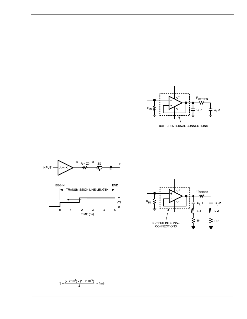
Measuring the length of a transmission line
An open transmission line can be used to measure the
length of a particular transmission line. As can be seen in
Figure 7
the line of interest has a certain length. A transient
is applied at T = 0 and at that point in time the wavefront
starts traveling with an amplitude of V/2 towards the end of
the line where it is reflected back to the startpoint.
To calculate the length of the line it is necessary to measure
immediately after the series termination resistor. The voltage
at that point remains at half nominal voltage, thus V/2, until
the reflection returns and the voltage jumps to V. During an
interval of 5ns the signal travels to the end of the line where
the wave front is reflected and returns to the measurement
point. During the time interval when the wavefront is travel-
ing to the end of the transmission line and back the voltage
has a value of V/2. This interval is 10ns. The length can be
calculated with the following formula: S = (V*T)/2
(5)
As calculated before in the section ’Driving more than one
input’ the signal travels 20cm/ns so in 5ns this distance
indicated distance is 1m. So this example is easily verified.
APPLYING A CAPACITIVE LOAD
The assumption of pure resistance for the purpose of con-
necting the output stage of a buffer or opamp to a load is
appropriate as a first approximation. Unfortunately that is
only a part of the truth. Associated with this resistor is a
capacitor in parallel and an inductor in series. Any capaci-
tance such as C
L
-1 which is connected directly to the output
stage is active in the loop gain as seen in
Figure 8
. Output
capacitance, present also at the minus input in the case of a
buffer, causes an increasing phase shift leading to instability
or even oscillation in the circuit.
Unfortunately the leads of the output capacitor also contain
series inductors which become more and more important at
high frequencies. At a certain frequency this series capacitor
and inductor forms an LC combination which becomes se-
ries resonant. At the resonant frequency the reactive com-
ponent vanishes leaving only the ohmic resistance (R-1 or
R-2) of the series L/C combination. (see
Figure 9
).
Consider a frequency sweep over the entire spectrum for
which the LMH6559 high frequency buffer is active. In the
first instance peaking occurs due to the parasitic capaci-
tance connected at the load whereas at higher frequencies
the effects of the series combination of L and C become
noticeable. This causes a distinctive dip in the output fre-
quency sweep and this dip varies depending upon the par-
ticular capacitor as seen in
Figure 10
.
20064146
FIGURE 7.
20064148
FIGURE 8.
20064149
FIGURE 9.
L
www.national.com
16
相關PDF資料 |
PDF描述 |
|---|---|
| LMH6559MFX | High-Speed, Closed-Loop Buffer |
| LMH6559MA | High-Speed, Closed-Loop Buffer |
| LMH6559MAX | High-Speed, Closed-Loop Buffer |
| LMH6570MA | 2:1 High Speed Video Multiplexer |
| LMH6570MAX | 2:1 High Speed Video Multiplexer |
相關代理商/技術參數 |
參數描述 |
|---|---|
| LMH6559MF/NOPB | 功能描述:運算放大器 - 運放 High-Speed, Closed- Loop Buffer RoHS:否 制造商:STMicroelectronics 通道數量:4 共模抑制比(最小值):63 dB 輸入補償電壓:1 mV 輸入偏流(最大值):10 pA 工作電源電壓:2.7 V to 5.5 V 安裝風格:SMD/SMT 封裝 / 箱體:QFN-16 轉換速度:0.89 V/us 關閉:No 輸出電流:55 mA 最大工作溫度:+ 125 C 封裝:Reel |
| LMH6559MFX | 制造商:Texas Instruments 功能描述:OP Amp Single GP 10V 5-Pin SOT-23 T/R |
| LMH6559MFX/NOPB | 功能描述:運算放大器 - 運放 RoHS:否 制造商:STMicroelectronics 通道數量:4 共模抑制比(最小值):63 dB 輸入補償電壓:1 mV 輸入偏流(最大值):10 pA 工作電源電壓:2.7 V to 5.5 V 安裝風格:SMD/SMT 封裝 / 箱體:QFN-16 轉換速度:0.89 V/us 關閉:No 輸出電流:55 mA 最大工作溫度:+ 125 C 封裝:Reel |
| LMH6560 | 制造商:NSC 制造商全稱:National Semiconductor 功能描述:Quad, High-Speed, Closed-Loop Buffer |
| LMH6560_04 | 制造商:NSC 制造商全稱:National Semiconductor 功能描述:Quad, High-Speed, Closed-Loop Buffer |
發布緊急采購,3分鐘左右您將得到回復。