- 您現在的位置:買賣IC網 > PDF目錄361044 > LMX2434 (National Semiconductor Corporation) PLLatinum Dual High Frequency Synthesizer for RF Personal Communications PDF資料下載
參數資料
| 型號: | LMX2434 |
| 廠商: | National Semiconductor Corporation |
| 英文描述: | PLLatinum Dual High Frequency Synthesizer for RF Personal Communications |
| 中文描述: | PLLatinum雙高頻率合成射頻個人通信 |
| 文件頁數: | 42/49頁 |
| 文件大小: | 943K |
| 代理商: | LMX2434 |
第1頁第2頁第3頁第4頁第5頁第6頁第7頁第8頁第9頁第10頁第11頁第12頁第13頁第14頁第15頁第16頁第17頁第18頁第19頁第20頁第21頁第22頁第23頁第24頁第25頁第26頁第27頁第28頁第29頁第30頁第31頁第32頁第33頁第34頁第35頁第36頁第37頁第38頁第39頁第40頁第41頁當前第42頁第43頁第44頁第45頁第46頁第47頁第48頁第49頁
2.0 Programming Description
(Continued)
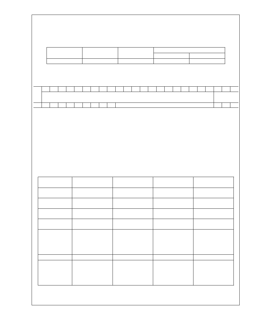
2.5.4 RF_PD - RF Synthesizer Powerdown (R1[23])
The RF_PD bit is used to switch the RF PLL between a powered up and powered down mode.
Furthermore, the RF_PD bit operates in conjuction with the RF_CPT bit to set a synchronous or an asynchronous powerdown
mode. Refer to
Section 2.4.4
for more details on how to program the RF_CPT bit.
Control Bit
Register Location
Description
Function
0
1
RF_PD
R1[23]
RF Powerdown
RF PLL Active
RF PLL Powerdown
2.6 R2 REGISTER
The R2 Register contains the RF_TOC control word. The RF_TOC is used to setup the RF syhnthesizer’s Fastlock circuitry. The
RF_TOC is a 12-bit binary counter programmable from 0 to 4095.
Reg
23
22
21
20
19
18
17
16
15
14
13
12
11
10
9
8
7
6
5
4
3
2
1
0
DATA[20:0] FIELD
ADDRESS
[2:0]
FIELD
R2
0
0
0
0
0
0
0
0
0
RF_TOC[11:0]
0
1
0
2.6.1 RF_TOC[0:11] - RF Synthesizer Timeout Counter (R2[14:3])
The FLoutRF pin can be configured as a general purpose CMOS TRI-STATE output or as a Fastlock output by programming the
RF_TOC appropriately. When the RF_TOC is programmed from 0 to 3, Automatic Fastlock is disabled, and the FLoutRF pin is
either configured as a general purpose CMOS TRI-STATE output or Manual Fastlock is enabled. When the RF_TOC is
programmed to 0, the FLoutRF pin will be in TRI-STATE (high impedance) mode. The charge pump current is then the value
specified by RF_CPG (R0[19]). When the RF_TOC is programmed to 1, the FLoutRF pin is pulled to a LOW state. The charge
pump current is then set to a HIGH gain state (RF_CPG bit = 1). This condition is known as the Manual Fastlock. When the
RF_TOC is programmed to 2, the FLout_RF pin will again be pulled to a LOW state, but this time the charge pump current is the
value specified by RF_CPG (R0[19]). When the RF_TOC is programmed to 3, the FLoutRF pin is pulled to a HIGH state. Again,
the charge pump current is the value specified by RF_CPG (R0[19]). When the RF_TOC is programmed from 4 to 4095, Fastlock
is enabled and the FLoutRF pin is pulled to a LOW state. Fastlock will time-out after the specified number of PFD events. At this
time, the FLoutRF pin will switch to TRI-STATE (high impedance) mode. The value programmed into RF_TOC represents the
number of PFD events that the RF synthesizer will spend in the Fastlock state. Note that any write to the RF_TOC requires a PFD
event on the RF synthesizer to latch the contents. This means that writes to the RF_TOC take effect synchronously with the next
PFD event.
RF_TOC[11:0]
FastLock Mode
Fastlock Period
[PFD Events]
N/A
FLoutRF Pin
Functionality/ State
General Purpose.
High Impedance State
General Purpose.
Logic LOW State
General Purpose.
Logic LOW State
General Purpose.
Logic HIGH State
FastLock.
Logic LOW State.
Switches to High
Impedance after 4 PFD
events
…
FastLock.
Logic LOW State.
Switches to High
Impedance after 4095
PFD events
I
CPoutRF
Magnitude
0
Disabled
I
CPoutRF
magnitude
controlled by R0[19]
I
CPoutRF
= 4 mA
1
Enabled
Manual Fastlock
Disabled
N/A
2
N/A
I
CPoutRF
magnitude
controlled by R0[19]
I
CPoutRF
magnitude
controlled by R0[19]
I
CPoutRF
= 4 mA
Switches to 1 mA after
4 PFD events
3
Disabled
N/A
4
Enabled
Automatic Fastlock
4
…
…
…
…
4095
Enabled
Automatic Fastlock
4095
I
CPoutRF
= 4 mA
Switches to 1 mA after
4095 PFD events
L
www.national.com
42
相關PDF資料 |
PDF描述 |
|---|---|
| LMX2434TM | PLLatinum Dual High Frequency Synthesizer for RF Personal Communications |
| LMX2434TMX | PLLatinum Dual High Frequency Synthesizer for RF Personal Communications |
| LMX2430SLEX | PLLatinum Dual High Frequency Synthesizer for RF Personal Communications |
| LMX2430TM | PLLatinum Dual High Frequency Synthesizer for RF Personal Communications |
| LMX2430TMX | PLLatinum Dual High Frequency Synthesizer for RF Personal Communications |
相關代理商/技術參數 |
參數描述 |
|---|---|
| LMX2434EVAL | 功能描述:時鐘和定時器開發工具 LMX2434 EVAL BOARD RoHS:否 制造商:Texas Instruments 產品:Evaluation Modules 類型:Clock Conditioners 工具用于評估:LMK04100B 頻率:122.8 MHz 工作電源電壓:3.3 V |
| LMX2434EVAL/NOPB | 功能描述:時鐘和定時器開發工具 LMX2434 EVAL BOARD RoHS:否 制造商:Texas Instruments 產品:Evaluation Modules 類型:Clock Conditioners 工具用于評估:LMK04100B 頻率:122.8 MHz 工作電源電壓:3.3 V |
| LMX2434SLEX | 制造商:Texas Instruments 功能描述:PLL Frequency Synthesizer Dual 500MHz to 5000MHz 20-Pin LAM UCSP T/R |
| LMX2434SLEX/NOPB | 功能描述:鎖相環 - PLL RoHS:否 制造商:Silicon Labs 類型:PLL Clock Multiplier 電路數量:1 最大輸入頻率:710 MHz 最小輸入頻率:0.002 MHz 輸出頻率范圍:0.002 MHz to 808 MHz 電源電壓-最大:3.63 V 電源電壓-最小:1.71 V 最大工作溫度:+ 85 C 最小工作溫度:- 40 C 封裝 / 箱體:QFN-36 封裝:Tray |
| LMX2434TM | 制造商:Texas Instruments 功能描述:PLL Frequency Synthesizer Dual 500MHz to 5000MHz 20-Pin TSSOP Rail |
發布緊急采購,3分鐘左右您將得到回復。