- 您現在的位置:買賣IC網 > Datasheet目錄43 > MAX5934EEE+ (Maxim Integrated)IC HOT-SWAP CONTROLLER 16-QSOP Datasheet資料下載
參數資料
| 型號: | MAX5934EEE+ |
| 廠商: | Maxim Integrated |
| 文件頁數: | 10/15頁 |
| 文件大小: | 268K |
| 描述: | IC HOT-SWAP CONTROLLER 16-QSOP |
| 產品培訓模塊: | Lead (SnPb) Finish for COTS Obsolescence Mitigation Program |
| 標準包裝: | 100 |
| 類型: | 熱交換控制器 |
| 應用: | 通用 |
| 內部開關: | 無 |
| 電源電壓: | 33 V ~ 80 V |
| 工作溫度: | -40°C ~ 85°C |
| 安裝類型: | 表面貼裝 |
| 封裝/外殼: | 16-SSOP(0.154",3.90mm 寬) |
| 供應商設備封裝: | 16-QSOP |
| 包裝: | 管件 |
Positive High-Voltage, Hot-Swap Controllers with
Selectable Fault Management and Status Polarity
10 ______________________________________________________________________________________
where:
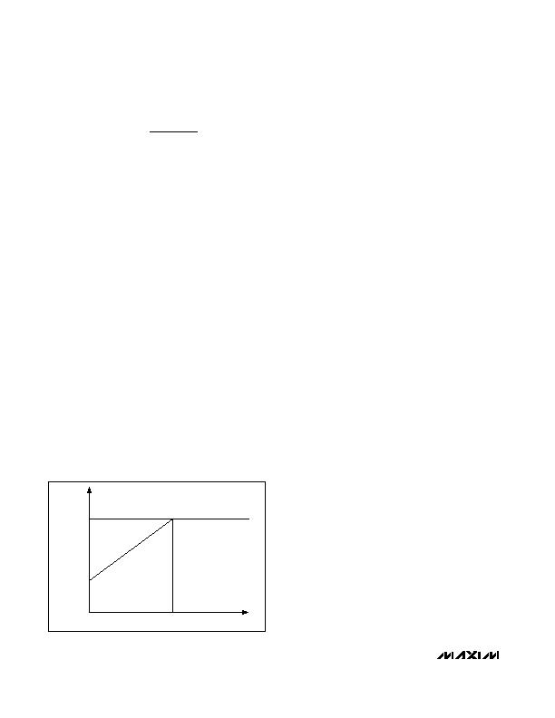
V
SENSETRIP
= V
IN
- V
SENSE
V
SENSETRIP
varies from a low of 12mV when the voltage
at FB1 = 0V and increases to 47mV as the voltage at
FB1 increases to 0.5V and beyond (see Figure 6).
Thus, the current limit is low at a low output voltage,
and increases as the output voltage reaches its final
value. This gradually increases the limiting load current
at startup and creates a foldback current limit under
overload or short-circuit conditions. See Figure 5 for
FB1 and R
SENSE
connections.
Power-Up Mode
During power-up, the MAX5934/MAX5934A gradually
turn on the external n-channel MOSFETs. The
MAX5934/MAX5934A monitor and provide current-limit
protection to the load at all times. The current limit is
programmable using an external current-sense resistor
connected from V
CC
to SENSE. The MAX5934/
MAX5934A feature current-limit foldback and duty-cycle
limit to ensure robust operation during load-fault and
short-circuit conditions (see the Detailed Description
and Overcurrent Protection sections).
TIMER
Connect an external capacitor from TIMER to ground to
set the maximum overcurrent timeout limit. When the volt-
age at TIMER reaches 1.233V, GATE goes low and the
75礎 pullup current turns off (see the Functional
Diagram). As a result, a preset pulldown current
(I
TIMERON
) discharges the capacitor. To reset the internal
fault latch, these two conditions must be met:
1) TIMERs voltage goes below 0.5V
2) ON goes low
When the current limit is not active, TIMER goes low by
the I
TIMERON
current source. After the current limit
becomes active, the I
TIMEROFF
pullup current source is
connected to TIMER and the voltage rises with a slope
of 75礎/C
TIMER
as long as the current limit remains
active. A capacitor from TIMER to GND (C
TIMER
) sets
the desired current-limit timeout:
T
LIMIT
= (C
TIMER
/ 75礎) x 1.233V
GATE
GATE provides a high-side gate drive for the external
n-channel MOSFET. An internal charge-pump circuit
guarantees at least 10V of gate drive for supply voltages
higher than 20V (MAX5934A) and a 4.5V gate drive for
supply voltages between 10.8V and 20V (MAX5934A)
(for the MAX5934, see the Electrical Characteristics
table). Connect an external capacitor from GATE to
ground to set the rising slope of the voltage at GATE.
The voltage at GATE is adjusted to maintain a constant
voltage across R
SENSE
when the current limit is reached
while the TIMER capacitor starts to charge. When the
voltage at TIMER exceeds 1.233V, the voltage at GATE
goes low.
The MAX5934/MAX5934A monitor voltages at ON, V
CC
,
and TIMER. GATE is pulled to GND whenever ON goes
low, or the V
CC
supply voltage decreases below the
UVLO threshold, or TIMER increases above the 1.233V
threshold.
Gate Voltage
The Gate Drive vs. Supply Voltage graph in the Typical
Operating Characteristics illustrates that GATE clamps
to a maximum of 18V above the input voltage. The
MAX5934 minimum gate-drive voltage is 10V at a mini-
mum input-supply voltage of 33V. The MAX5934A mini-
mum gate-drive voltage is 4.5V at a minimum supply of
10.8V. Therefore, a logic-level MOSFET must be used if
the input supply is below 20V.
Fault Management (LATCH/RETRY)
The MAX5934/MAX5934A feature either latched-off or
autoretry fault management configurable by the
LATCH/RETRY input. To select automatic restart after a
circuit-breaker fault, drive LATCH/RETRY high (above
V
LRIH
) or leave it floating (see Figure 5).
I
V
R
LOAD
SENSETRIP
SENSE
=
0.5V
0V
12mV
47mV
V
CC
- V
SENSE
V
FB
Figure 6. Current-Limit Sense Voltage vs. Feedback Voltage
相關PDF資料 |
PDF描述 |
|---|---|
| MAX5935EAX+ | IC CTRLR POWER QUAD 36-SSOP |
| MAX5937LCESA+ | IC HOT-SWAP CTRLR -48V 8-SOIC |
| MAX5938LEEE+ | IC HOT-SWAP CTRLR -48V 16-QSOP |
| MAX5939EESA+ | IC HOT-SWAP CTRLR -48V 8-SOIC |
| MAX5946LETX+T | IC CNTRLR PCI EXP DL 36TQFN |
相關代理商/技術參數 |
參數描述 |
|---|---|
| MAX5934EEE+ | 功能描述:熱插拔功率分布 Positive Hot-Swap Controller RoHS:否 制造商:Texas Instruments 產品:Controllers & Switches 電流限制: 電源電壓-最大:7 V 電源電壓-最小:- 0.3 V 工作溫度范圍: 功率耗散: 安裝風格:SMD/SMT 封裝 / 箱體:MSOP-8 封裝:Tube |
| MAX5934EEE+T | 功能描述:熱插拔功率分布 Positive Hot-Swap Controller RoHS:否 制造商:Texas Instruments 產品:Controllers & Switches 電流限制: 電源電壓-最大:7 V 電源電壓-最小:- 0.3 V 工作溫度范圍: 功率耗散: 安裝風格:SMD/SMT 封裝 / 箱體:MSOP-8 封裝:Tube |
| MAX5934EEE-T | 功能描述:熱插拔功率分布 RoHS:否 制造商:Texas Instruments 產品:Controllers & Switches 電流限制: 電源電壓-最大:7 V 電源電壓-最小:- 0.3 V 工作溫度范圍: 功率耗散: 安裝風格:SMD/SMT 封裝 / 箱體:MSOP-8 封裝:Tube |
| MAX5935CAX | 功能描述:熱插拔功率分布 RoHS:否 制造商:Texas Instruments 產品:Controllers & Switches 電流限制: 電源電壓-最大:7 V 電源電壓-最小:- 0.3 V 工作溫度范圍: 功率耗散: 安裝風格:SMD/SMT 封裝 / 箱體:MSOP-8 封裝:Tube |
| MAX5935CAX+ | 功能描述:熱插拔功率分布 Quad Network Power Controller RoHS:否 制造商:Texas Instruments 產品:Controllers & Switches 電流限制: 電源電壓-最大:7 V 電源電壓-最小:- 0.3 V 工作溫度范圍: 功率耗散: 安裝風格:SMD/SMT 封裝 / 箱體:MSOP-8 封裝:Tube |
發布緊急采購,3分鐘左右您將得到回復。