- 您現在的位置:買賣IC網 > PDF目錄16786 > MAX9738EVKIT+ (Maxim Integrated Products)KIT EVALUATION FOR MAX9738 PDF資料下載
參數資料
| 型號: | MAX9738EVKIT+ |
| 廠商: | Maxim Integrated Products |
| 文件頁數: | 2/14頁 |
| 文件大小: | 0K |
| 描述: | KIT EVALUATION FOR MAX9738 |
| 產品培訓模塊: | Lead (SnPb) Finish for COTS Obsolescence Mitigation Program |
| 標準包裝: | 1 |
| 放大器類型: | G 類 |
| 輸出類型: | 1-通道(單聲道) |
| 電源電壓: | 2.7 V ~ 5.5 V |
| 工作溫度: | -45°C ~ 85°C |
| 板類型: | 完全填充 |
| 已用 IC / 零件: | MAX9738 |
| 已供物品: | 板 |
| 相關產品: | MAX9738EWP+TG45-ND - IC AMP AUDIO PWR MONO G 20WLP |
MAX9738
Shutdown Mode
The MAX9738 has a shutdown mode that reduces power
consumption and extends battery life. Driving SHDN low
places the MAX9738 in a low-power (0.6μA) shutdown
mode. Connect SHDN to VDD for normal operation.
Click-and-Pop Suppression
The MAX9738 Class G amplifier features Maxim’s com-
prehensive, industry-leading click-and-pop suppres-
sion. During startup, the click-and-pop suppression
circuitry eliminates any audible transient sources inter-
nal to the device.
Applications Information
Differential Input Amplifier
The MAX9738 features a differential input configuration,
making the device compatible with many CODECs, and
offering improved noise immunity over a single-ended
input amplifier. In devices such as PCs, noisy digital
signals can be picked up by the amplifier’s input
traces. The signals appear at the amplifiers’ inputs as
common-mode noise. A differential input amplifier
amplifies the difference of the two inputs, and signals
common to both inputs are canceled out. When config-
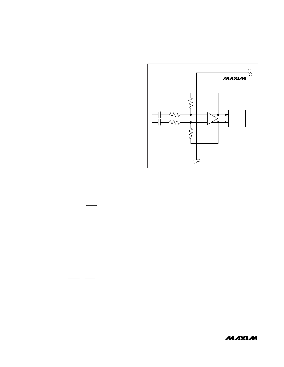
ured for differential inputs, the voltage gain of the
MAX9738 is set by:
where AV is the desired voltage gain in dB. RIN+ should
be equal to RIN-, and RFB+ should be equal to RFB-.
The Class G output stage has a fixed gain of 4V/V
(12dB). Any gain or attenuation set by the external
input stage resistors add to or subtract from this fixed
gain. See Figure 2.
In differential input configurations, the common-mode
rejection ratio (CMRR) is primarily limited by the exter-
nal resistor and capacitor matching. Ideally, to achieve
the highest possible CMRR the following external com-
ponents should be selected where:
and
Driving a Ceramic Speaker
Applications that require a thin profile, such as today’s
mobile phones, demand that components have a small
form factor. Dynamic loudspeakers that use a cone and
voice coil typically cannot conform to the height
requirements. The option for these applications is to
use a ceramic/piezoelectric loudspeaker.
Ceramic speakers are much more capacitive than a
conventional loudspeaker. Typical capacitance values
for such a speaker can be greater than 1μF. High peak-
to-peak voltage drive is required to achieve acceptable
sound pressure levels. The high output voltage require-
ment coupled with the capacitive nature of the speaker
demand that the amplifier supply much more current at
high frequencies than at lower frequencies. Above 5kHz
the typical speaker impedance can be less than 20
Ω.
The MAX9738 is ideal for driving a capacitive ceramic
speaker. The high boost converter current limit allows
for a flat frequency response out to 20kHz while main-
taining high output voltage swings. Figure 3 shows a
typical circuit for driving a ceramic speaker.
A 20
Ω series resistance is required between the ampli-
fier output and the ceramic speaker load to ensure the
output of the amplifier sees some fixed resistance at
high frequencies when the speaker is essentially an
electrical short.
CC
IN+
IN-
=
R
FB+
IN+
FB-
IN-
=
A
R
dB
V
FB_
IN_
24 (
=×
()
0log[
)]
16VP-P Class G Amplifier with
Inverting Boost Converter
10
______________________________________________________________________________________
MAX9738
+
IN+
FB+
RIN+
RIN-
CIN+
CIN-
IN-
FB-
-
CLASS G
OUTPUT
STAGE
RFB+
RFB-
Figure 2. Gain Setting
相關PDF資料 |
PDF描述 |
|---|---|
| 1641-181K | COIL .18UH MOLDED SHIELDED |
| MC1403BD | IC VREF SERIES PREC 2.5V 8-SOICN |
| EEC26DRYN-S734 | CONN EDGECARD 52POS DIP .100 SLD |
| GCC18DRYI | CONN EDGECARD 36POS DIP .100 SLD |
| V300B12E150BG3 | CONVERTER MOD DC/DC 12V 150W |
相關代理商/技術參數 |
參數描述 |
|---|---|
| MAX9738EVKIT+ | 功能描述:放大器 IC 開發工具 MAX9738 Eval Kit RoHS:否 制造商:International Rectifier 產品:Demonstration Boards 類型:Power Amplifiers 工具用于評估:IR4302 工作電源電壓:13 V to 23 V |
| MAX9738EWP+T | 制造商:Maxim Integrated Products 功能描述:16VP-P CLASS G AMPLIFIER WITH INVER - Tape and Reel |
| MAX9738EWP+TG45 | 功能描述:音頻放大器 16VP-P Class G Amplifier RoHS:否 制造商:STMicroelectronics 產品:General Purpose Audio Amplifiers 輸出類型:Digital 輸出功率: THD + 噪聲: 工作電源電壓:3.3 V 電源電流: 最大功率耗散: 最大工作溫度: 安裝風格:SMD/SMT 封裝 / 箱體:TQFP-64 封裝:Reel |
| MAX973C/D | 功能描述:校驗器 IC RoHS:否 制造商:STMicroelectronics 產品: 比較器類型: 通道數量: 輸出類型:Push-Pull 電源電壓-最大:5.5 V 電源電壓-最小:1.1 V 補償電壓(最大值):6 mV 電源電流(最大值):1350 nA 響應時間: 最大工作溫度:+ 125 C 安裝風格:SMD/SMT 封裝 / 箱體:SC-70-5 封裝:Reel |
| MAX973CPA | 功能描述:校驗器 IC RoHS:否 制造商:STMicroelectronics 產品: 比較器類型: 通道數量: 輸出類型:Push-Pull 電源電壓-最大:5.5 V 電源電壓-最小:1.1 V 補償電壓(最大值):6 mV 電源電流(最大值):1350 nA 響應時間: 最大工作溫度:+ 125 C 安裝風格:SMD/SMT 封裝 / 箱體:SC-70-5 封裝:Reel |
發布緊急采購,3分鐘左右您將得到回復。