- 您現在的位置:買賣IC網 > PDF目錄371030 > MC34016 (Motorola, Inc.) Cordless Universal Telephone Interface PDF資料下載
參數資料
| 型號: | MC34016 |
| 廠商: | Motorola, Inc. |
| 英文描述: | Cordless Universal Telephone Interface |
| 中文描述: | 通用無繩電話接口 |
| 文件頁數: | 3/16頁 |
| 文件大小: | 315K |
| 代理商: | MC34016 |
MC34016
3
MOTOROLA ANALOG IC DEVICE DATA
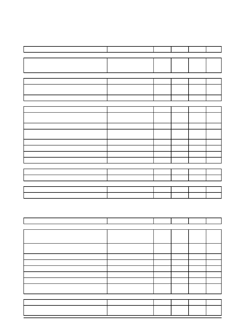
DC ELECTRICAL CHARACTERISTICS
(All parameters are specified with Bit 0 of Register 1 set to 1, the rest of the
bits in both registers set to 0, TA = 25
°
C, VCC = 5.0 V, Iline = 15 mA, f = 1.0 kHz, Test Circuit in Figure 9, unless otherwise noted.)
Parameter
Condition
Min
Typ
Max
Unit
VOLTAGE REGULATION
Line Voltage Vline
Iline = 60 mA
3.7
4.2
6.6
4.0
4.5
6.85
4.3
4.8
7.1
V
Iline = 5.0 mA
Iline = 15 mA
CURRENT REGULATION
(Bit 4, Reg.1 = 1; Bit 1, Reg. 2 = 1; RAGC = 47 k
)
Line Voltage Vline
Iline = 15 mA
4.2
4.5
4.8
V
Line Current Iline
Vline = 35 V
–
–
35
56
–
–
mA
Vline = 10 V
Line Current Iline in Protection Mode
DC BIASING
Vline = 70 V
–
28
–
mA
Operating Supply Voltage VCC
–
3.0
–
5.5
V
Current Consumption from VCC
VCC = 5.0 V, all Bits to 0
–
–
3.0
3.5
4.0
4.5
mA
VCC = 3.0 V, all Bits to 0
Source Capabiltiy Pin LAO in Speech Mode
VLAO = 0.7 V
VLAO = 0.7 V
–
–
–2.0
mA
Source Capability Pin LAO in Dialing Mode
(Bit 5, Reg. 1 = 1)
–
–
–5.0
mA
Internal Pull Down Resistor at Pin LAO
–
–
11
–
k
Bias Voltage at Pins HYL, HYS and LAI
–
–
1.3
–
V
Bias Voltage at Pins Tx1 and Tx2
Bias Voltage at Pins Rx1 and Rx2
LOGIC INPUTS
–
–
1.5
–
V
–
–
1.3
–
V
Logic Low Level Pins Clk, Data, BEN
–
–
–
0.6
V
Logic High Level Pins Clk, Data, BEN
–
2.2
–
–
V
LOGIC OUTPUTS
Source Capability from Pins HKSW, Out1, Out2
Output Voltage at VCC – 1.3 V
Output Voltage at 0.5 V
–
–
–1.0
mA
Sink Capability into Pins HKSW, Out1, Out2
5.0
–
–
mA
AC ELECTRICAL CHARACTERISTICS
(All parameters are specified with Bit 0 of Register 1 set to 1, the rest of the
bits in both registers set to 0, TA = 25
°
C, VCC = 5.0 V, Iline = 15 mA, f = 1.0 kHz, Test Circuit in Figure 9, unless otherwise noted.)
Parameter
Condition
Min
Typ
Max
Unit
TRANSMIT CHANNEL
Transmit Gain from VTx to Vline
MC34016P
MC34016DW
VTx = 0.1 Vrms
–1.0
–1.25
0.25
–0.20
1.5
0.85
dB
Gain Variation with Line Current Referred to
Iline = 15 mA with the AGC Function Switched “Off”
Iline = 70 mA,
Bit 0, Reg. 2 = 1
–0.7
–
0.7
dB
Gain Increase in 6.0 dB Mode
Bit 4, Reg. 2 = 1
5.3
6.0
6.7
dB
Gain Reduction in Mute Condition
Bit 2, Reg. 2 = 1
65
–
–
dB
Input Impedance at Tx1 or Tx2
Maximum Input Swing for VTx
THD at the Line (Vline)
Psophometrically Weighted Noise Level at the Line
(Vline)
–
–
30
–
k
THD
≤
2%
–
4.0
–
Vpp
VTx = 3.0 dBm
200
Between Tx1 and Tx2
–
1.0
2.0
%
–
–79
–
dBmp
RECEIVE CHANNEL
Receive Gain from Vline to VRx
Gain Variation with Line Current Referred to
Iline = 15 mA with the AGC Function Switched “Off”
Vline = 0.1 Vrms
Iline = 70 mA,
Bit 0, Reg. 2 = 1
–1.0
0
1.0
dB
–0.7
–
0.7
dB
相關PDF資料 |
PDF描述 |
|---|---|
| MC3401 | QUAD SINGLE SUPPLY OPERATIONAL AMPLIFIERS |
| MC34025DW | Battery-Backup Supervisors for RAM Retention 8-MSOP -40 to 85 |
| MC33025 | High Speed Double-Ended PWM Controller |
| MC33025DW | High Speed Double-Ended PWM Controller |
| MC33025P | High Speed Double-Ended PWM Controller |
相關代理商/技術參數 |
參數描述 |
|---|---|
| MC34016DW | 制造商:MOTOROLA 制造商全稱:Motorola, Inc 功能描述:Cordless Universal Telephone Interface |
| MC34016DWR2 | 制造商:Motorola Inc 功能描述:TELECOM-SLIC, PDSO20 |
| MC34016P | 制造商:MOTOROLA 制造商全稱:Motorola, Inc 功能描述:Cordless Universal Telephone Interface |
| MC34017 | 制造商:MOTOROLA 制造商全稱:Motorola, Inc 功能描述:TELEPHONE TONE RINGER BIPOLAR LINEAR/I2L |
| MC340171D | 制造商:MOT 功能描述:* |
發布緊急采購,3分鐘左右您將得到回復。