- 您現在的位置:買賣IC網 > PDF目錄371035 > MC44007P (MOTOROLA INC) CHROMA 4 VIDEO PROCESSOR PDF資料下載
參數資料
| 型號: | MC44007P |
| 廠商: | MOTOROLA INC |
| 元件分類: | 消費家電 |
| 英文描述: | CHROMA 4 VIDEO PROCESSOR |
| 中文描述: | SPECIALTY CONSUMER CIRCUIT, PDIP40 |
| 封裝: | PLASTIC, DIP-40 |
| 文件頁數: | 13/40頁 |
| 文件大小: | 491K |
| 代理商: | MC44007P |
第1頁第2頁第3頁第4頁第5頁第6頁第7頁第8頁第9頁第10頁第11頁第12頁當前第13頁第14頁第15頁第16頁第17頁第18頁第19頁第20頁第21頁第22頁第23頁第24頁第25頁第26頁第27頁第28頁第29頁第30頁第31頁第32頁第33頁第34頁第35頁第36頁第37頁第38頁第39頁第40頁
MC44002 MC44007
13
MOTOROLA ANALOG IC DEVICE DATA
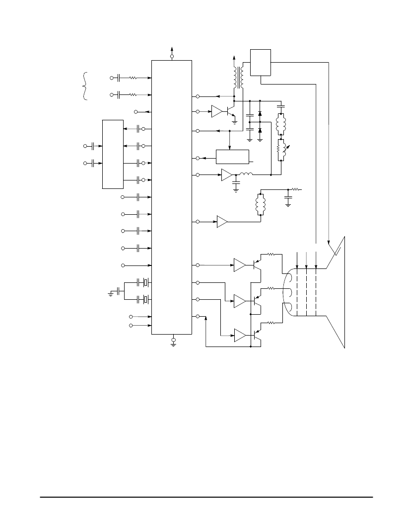
Figure 5. Connection to TV Chassis
B
B
G
G
R
R
G2
G1
EHT
V O/P
Stage
V-Scan
Coils
26 V
Line O/P
Stage
E-W
Amplifier
Diode Modulator
Linearity
H-Scan
Coils
Focus
EHT
Tripler
5.0 V
Line Output
Transformer
H-Flyback
H-Drive
Anode Current
E-W Drive
V-Drive
Analog
Contrast
R-O/P
G-O/P
B-O/P
Feedback
0 V
Data
Clock
14.3 MHz
17.7 MHz
Fast Commutate
B In
G In
R In
Y2 In
Ext B-Y
Ext R-Y
B-Y In
R-Y In
B-Y Out
R-Y Out
Y1 Out
Video 2
Video 1
G3
I2C Bus
MC44002/7
M
H.T.
Comp Video
or
S-VHS
Beam Current
Limitation
12 V
The next stage is called the color difference stage where a
number of control functions are carried out together with
matrixing of the components to derive RGB signals. At this
point a number of auxiliary signals may also be switched in,
again all under MCU control. External RGB (text) and Fast
Commutate enter here; also an external luminance (Y2) may
be used instead of Y1. External R-Y and B-Y are switched in
via the delay line circuit to save pins on the main device. The
Y2 and External R-Y, B-Y will obviously be of considerable
benefit from the system point of view for use with external
decoders.
The final stage of video processing is the RGB outputs which
drive the high voltage amplifiers connected to the tube
cathodes. These outputs are controlled by a sophisticated
digital servo-loop which is maintained and stabilized by a
sequentially sampled beam current feedback system.
Automatic gray scale control is featured as a part of this system.
Both horizontal and vertical timebases are incorporated
into the MC44002/7 and control is via the I2C bus. The
horizontal timebase employs a dual loop system of a PLL and
variable phase shifter, and the vertical uses a countdown
system. For the vertical, a field rate sawtooth is available
which is used to drive an external power amplifier with
flyback generator (usually a single IC). The line output
consists of a pulse which drives a conventional line output
stage in the normal way. The line flyback pulse is sensed and
used by the second loop for horizontal phase shift.
Where E-W correction is required, a parabola waveform is
available for this which, with the addition of a power amplifier,
can be used with a diode modulator type line output stage for
dynamic width and E-W control. The bottom of the EHT
overwinding is returned to the MC44002/7 and is used for
anode current monitoring.
Fast beam current limitation is also made possible by the
use of an analog contrast control.
A much more detailed description of each stage of the
MC44002/7 will be found in the next section. Information on
the delay line is to be found in its own data sheet.
相關PDF資料 |
PDF描述 |
|---|---|
| MC44007 | CHROMA 4 VIDEO PROCESSOR |
| MC44035FTB | MULTISTANDARD VIDEO SIGNAL PROCESSOR WITH INTEGRATED CHROMA DELAY LINE |
| MC44030FTB | MULTISTANDARD VIDEO SIGNAL PROCESSOR WITH INTEGRATED CHROMA DELAY LINE |
| MC44030P | MULTISTANDARD VIDEO SIGNAL PROCESSOR WITH INTEGRATED CHROMA DELAY LINE |
| MC44035P | MULTISTANDARD VIDEO SIGNAL PROCESSOR WITH INTEGRATED CHROMA DELAY LINE |
相關代理商/技術參數 |
參數描述 |
|---|---|
| MC4401 | 制造商:SHENZHENFREESCALE 制造商全稱:ShenZhen FreesCale Electronics. Co., Ltd 功能描述:P-Channel 30-V (D-S) MOSFET Low thermal impedance |
| MC44011 | 制造商:MOTOROLA 制造商全稱:Motorola, Inc 功能描述:Chroma 4 Multistandard Video Processor |
| MC44011FB | 制造商:MOTOROLA 制造商全稱:Motorola, Inc 功能描述:BUS CONTROLLED MULTISTANDARD VIDEO PROCESSOR |
| MC44011FN | 制造商:MOTOROLA 制造商全稱:Motorola, Inc 功能描述:Chroma 4 Multistandard Video Processor |
| MC4403 | 制造商:SHENZHENFREESCALE 制造商全稱:ShenZhen FreesCale Electronics. Co., Ltd 功能描述:P-Channel 20-V (D-S) MOSFET High performance trench technology |
發布緊急采購,3分鐘左右您將得到回復。