- 您現在的位置:買賣IC網 > PDF目錄382324 > MF5CWM (NATIONAL SEMICONDUCTOR CORP) MF5 Universal Monolithic Switched Capacitor Filter PDF資料下載
參數資料
| 型號: | MF5CWM |
| 廠商: | NATIONAL SEMICONDUCTOR CORP |
| 元件分類: | 運動控制電子 |
| 英文描述: | MF5 Universal Monolithic Switched Capacitor Filter |
| 中文描述: | SWITCHED CAPACITOR FILTER, RESISTOR PROGRAMMABLE, UNIVERSAL, PDSO14 |
| 封裝: | SO-14 |
| 文件頁數: | 5/16頁 |
| 文件大小: | 293K |
| 代理商: | MF5CWM |
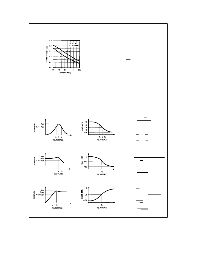
Typical Performance
Characteristics
(Continued)
Supply Current vs Temperature
TL/H/5066–4
1.0 Definitions of Terms
f
CLK
:
the frequency of the external clock signal applied to
pin 8.
f
o
:
center frequency of the second order function complex
pole pair. f
o
is measured at the bandpass output of the MF5,
and is the frequency of maximum bandpass gain. (Figure 1).
f
notch
:
the frequency of minimum (ideally zero) gain at the
notch output.
f
z
:
the center frequency of the second order complex zero
pair, if any. If f
z
is different from f
o
and if Q
z
is high, it can be
observed as the frequency of a notch at the allpass output.
(Figure 10).
Q:
‘‘quality factor’’ of the 2nd order filter. Q is measured at
the bandpass output of the MF5 and is equal to f
o
divided by
the
b
3dB bandwidth of the 2nd order bandpass filter (Fig-
ure 1 ). The value of Q determines the shape of the 2nd
order filter responses as shown in Figure 6.
Q
z
:
the quality factor of the second order complex zero pair,
if any. Q
z
is related to the allpass characteristic, which is
written:
H
AP
(s)
e
H
OAP
s
2
b
s
0
o
Q
z
a
0
o2
s
2
a
s
0
o
Q
a
0
o2
where Q
z
e
Q for an all-pass response.
H
OBP
:
the gain (in V/V) of the bandpass output at f
e
f
o
.
H
OLP
:
the gain (in V/V) of the lowpass output as f
x
0 Hz
(Figure 2 ).
H
:
the gain (in V/V) of the highpass output as
f
x
f
clk
/2 (Figure 3 ).
H
ON
x
0 Hz and
as f
x
f
clk
/2, when the notch filter has equal gain above
and below the center frequency (Figure 4 ). When the low-
frequency gain differs from the high-frequency gain, as in
modes 2 and 3a (Figures 11 and 8 ), the two quantities be-
low are used in place of H
ON
.
H
ON1
:
the gain (in V/V) of the notch output as f
x
0 Hz.
H
ON2
:
the gain (in V/V) of the notch output as f
x
f
clk
/2.
(a)
TL/H/5066–5
(b)
TL/H/5066–6
H
BP
(s)
e
H
OBP
a
0
#
0
o
Q
2Q
J
s
s
2
a
s
0
o
f
o
e
0
f
L
f
H
Q
a
0
o2
2Q
J
Q
e
f
o
f
H
b
f
L
;
f
L
e
f
o
#
b
1
2Q
1
2
a
1
J
f
H
e
f
o
#
1
2Q
a
0
#
1
2
a
1
J
0
o
e
2
q
f
o
FIGURE 1. 2nd-Order Bandpass Response
(a)
TL/H/5066–7
(b)
TL/H/5066–8
H
LP
(s)
e
H
OLP
0
o2
s
2
a
s
0
o
Q
a
0
o2
f
c
e
f
o
c
0
#
1
b
1
2Q
2
J
a
0
#
1
b
1
2Q
2
J
2
a
1
f
p
e
f
o
0
1
b
1
Q
0
1
b
2Q
2
H
OP
e
H
OLP
c
1
1
1
4Q
2
FIGURE 2. 2nd-Order Low-Pass Response
(a)
TL/H/5066–9
FIGURE 3. 2nd-Order High-Pass Response
(b)
TL/H/5066–10
H
HP
(s)
e
f
p
e
f
o
c
D
0
1
b
H
OHP
s
2
s
2
a
s
0
o
Q
a
0
o2
f
c
e
f
o
c
D
0
#
1
b
1
2Q
2
J
a
0
#
1
b
1
2Q
2
J
2
a
1
(
b
1
1
2Q
2
(
b
1
H
OP
e
H
OHP
c
1
1
Q
0
1
b
1
4Q
2
5
相關PDF資料 |
PDF描述 |
|---|---|
| MF600SWI | Mirco Filter For ADSL CPE Side |
| MF601F | Mirco Filter For ADSL CPE Side |
| MF602F | Mirco Filter For ADSL CPE Side |
| MF609 | The in-Line Micro filter |
| MF609A | The in-Line Micro filter |
相關代理商/技術參數 |
參數描述 |
|---|---|
| MF6 | 制造商:NSC 制造商全稱:National Semiconductor 功能描述:6th Order Switched Capacitor Butterworth Lowpass |
| MF6. 3FD101MD13TP | 制造商:nippon chemicon 功能描述: |
| MF6.3FC101MD13TP | 制造商:UCC 功能描述: 制造商:United Chemi-Con Inc 功能描述: |
| MF6.3FC22RMD6TP | 制造商:United Chemi-Con Inc 功能描述: |
| MF60 | 制造商:RIEDON 制造商全稱:Riedon Powertron 功能描述:Film Resistors |
發布緊急采購,3分鐘左右您將得到回復。