- 您現在的位置:買賣IC網 > Datasheet目錄44 > MIC2086-MBQS TR (Micrel Inc)IC CTRLR HOW SWAP SGL 20-QSOP Datasheet資料下載
參數資料
| 型號: | MIC2086-MBQS TR |
| 廠商: | Micrel Inc |
| 文件頁數: | 21/29頁 |
| 文件大小: | 1008K |
| 描述: | IC CTRLR HOW SWAP SGL 20-QSOP |
| 標準包裝: | 2,500 |
| 類型: | 熱交換控制器 |
| 應用: | 通用型 Infiniband? |
| 內部開關: | 無 |
| 電源電壓: | 2.3 V ~ 16.5 V |
| 工作溫度: | -40°C ~ 85°C |
| 安裝類型: | 表面貼裝 |
| 封裝/外殼: | 20-SSOP(0.154",3.90mm 寬) |
| 供應商設備封裝: | 20-QSOP |
| 包裝: | 帶卷 (TR) |
| 其它名稱: | MIC2086-MBQSTR MIC2086-MBQSTR-ND |
第1頁第2頁第3頁第4頁第5頁第6頁第7頁第8頁第9頁第10頁第11頁第12頁第13頁第14頁第15頁第16頁第17頁第18頁第19頁第20頁當前第21頁第22頁第23頁第24頁第25頁第26頁第27頁第28頁第29頁
Micrel, Inc.
MIC2085/2086
May 2006
21
M9999-050406
(408) 955-1690
Auto-Retry Upon Overcurrent Faults
The MIC2085/86 can be configured for automatic restart
after a fault condition. Placing a diode between the ON
and/FAULT pins, as shown in Figure 9, will enable the
auto-restart capability of the controller. When an
application is configured for auto-retry, the overcurrent
timer should be set to minimize the duty cycle of the
overcurrent response to prevent thermal runaway of the
power MOSFET. See
MOSFET Transient Thermal
Issues
section for further detail. A limited duty cycle is
achieved when the overcurrent timer duration (t
OCSLOW
) is
much less than the start-up delay timer duration (t
START
)
and is calculated using the following equation:
100%
t
t
Cycle
Duty
Retry
Auto
START
OCSLOW
?/DIV>
=
(10)
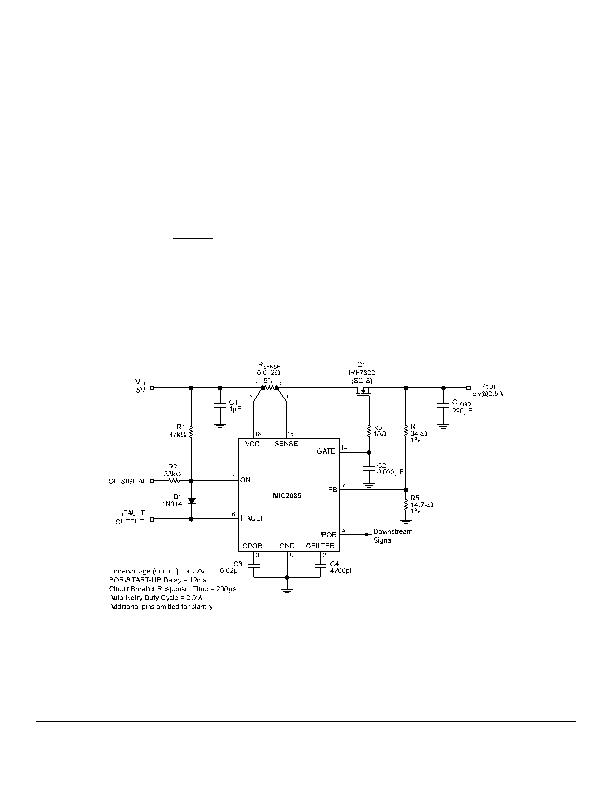
An InfiniBand" Application Circuit
The circuit in Figure 10 depicts a single 50W
InfiniBand" module using the MIC2085 controller. An
InfiniBand" backplane distributes bulk power to multiple
plug-in modules that employ DC/DC converters for local
supply requirements. The circuit in Figure 10 distributes
12V from the backplane to the MIC2182 DC/DC
converter that steps down +12V to+3.3V for local bias.
The pass transistor, Q1, isolates theMIC2182s input
capacitance during module plug-in and allows the
backplane to accommodate additional plug-in modules
without affecting the other modules on the backplane.
The two control input signals are VBxEn_L (active LOW)
and a Local Power Enable (active HIGH). The MIC2085
in the circuit of Figure 10 performs a number of
functions. The gate output of Q1 is enabled by the two
bit input signal VBxEn_L, Local Power Enable = [0,1].
Also, the MIC2085 limits the drain current of Q1 to 7A,
monitors VB_In for an overvoltage condition greater than
16V, and enables the MIC2182 DC/DC converter
downstream to supply a local voltage rail. The
uncommitted comparator is used to monitor VB_In for an
undervoltage condition of less than 10V, indicated by a
logic LOW at the comparator output (COMPOUT).
COMPOUT may be used to control a downstream
device such as another DC/DC converter. Additionally,
the MIC2085 is configured for auto-retry upon an
overcurrent fault condition by placing a diode (D1)
between the /FAULT and ON pins of the controller.
Figure 9. Auto-Retry Configuration
相關PDF資料 |
PDF描述 |
|---|---|
| MIC2225-4OYMT TR | IC REG DL BUCK/LINEAR 10TMLF |
| MIC2310-2ZTS TR | IC HOT SWAP CTLR 2CHAN 24TSSOP |
| MIC2341-2YTQ | IC HOT PLUG CTLR DUAL PCI 48TQFP |
| MIC2569YQS TR | IC POWER SWITCH CABLECARD 16QSOP |
| MIC2583R-MBQS TR | IC CTRLR HOT SWAP 200MV 16-QSOP |
相關代理商/技術參數 |
參數描述 |
|---|---|
| MIC2086-XBQS | 制造商:MICREL 制造商全稱:Micrel Semiconductor 功能描述:Single Channel Hot Swap Controllers |
| MIC2090 | 制造商:MICREL 制造商全稱:Micrel Semiconductor 功能描述:Current Limiting Power Distribution Switches |
| MIC2090_11 | 制造商:MICREL 制造商全稱:Micrel Semiconductor 功能描述:Current Limiting Power Distribution Switches |
| MIC2090-1YM5 | 制造商:MICREL 制造商全稱:Micrel Semiconductor 功能描述:Current Limiting Power Distribution Switches |
| MIC2090-1YM5 TR | 功能描述:電源開關 IC - USB 50mA Current Limiting Power Distribution Switch RoHS:否 制造商:Micrel 電源電壓-最小:2.7 V 電源電壓-最大:5.5 V 最大工作溫度:+ 85 C 最小工作溫度:- 40 C 封裝 / 箱體:SOIC-8 封裝:Tube |
發布緊急采購,3分鐘左右您將得到回復。