- 您現在的位置:買賣IC網 > PDF目錄361091 > NCP1406SNT1G (ON SEMICONDUCTOR) 25 V/25 mA PFM Step−Up DC−DC Converter PDF資料下載
參數資料
| 型號: | NCP1406SNT1G |
| 廠商: | ON SEMICONDUCTOR |
| 元件分類: | 穩壓器 |
| 英文描述: | 25 V/25 mA PFM Step−Up DC−DC Converter |
| 中文描述: | 1.5 A SWITCHING REGULATOR, 1000 kHz SWITCHING FREQ-MAX, PDSO5 |
| 封裝: | LEAD FREE, SC-59, SOT-23, TSOP-5 |
| 文件頁數: | 15/23頁 |
| 文件大?。?/td> | 224K |
| 代理商: | NCP1406SNT1G |
NCP1406
http://onsemi.com
15
switches on, the capacitor C1 is effectively connected like
a reversed battery and C1 discharges the stored charge
through the R
DS(on)
of the internal MOSFET and D3 to
charge up C
OUT
and builds up a negative voltage at V
OUT
.
Since the negative voltage output is not directly monitored
by the NCP1406, the output load regulation of the negative
output is not as good as the standard positive output circuit.
The resistance values of the resistors of the voltage divider
can be onetenth of those used in the positive output circuit
in order to improve the regulation at light load.
The application circuit in Figure 54, is actually the
combination of the application circuits in Figures 50 and
51.
StepDown Converter
NCP1406 can be configured as a simple stepdown
converter by using the opendrain LX pin to drive an
external PCh MOSFET as shown in Figure 52. The
resistor R
GS
is used to switch off the PCh MOSFET during
the switchoff period. Too small a resistance value should
not be used for R
GS
, otherwise, the efficiency will be
reduced. R
GS
should be in the range of 510 to 5.1 k .
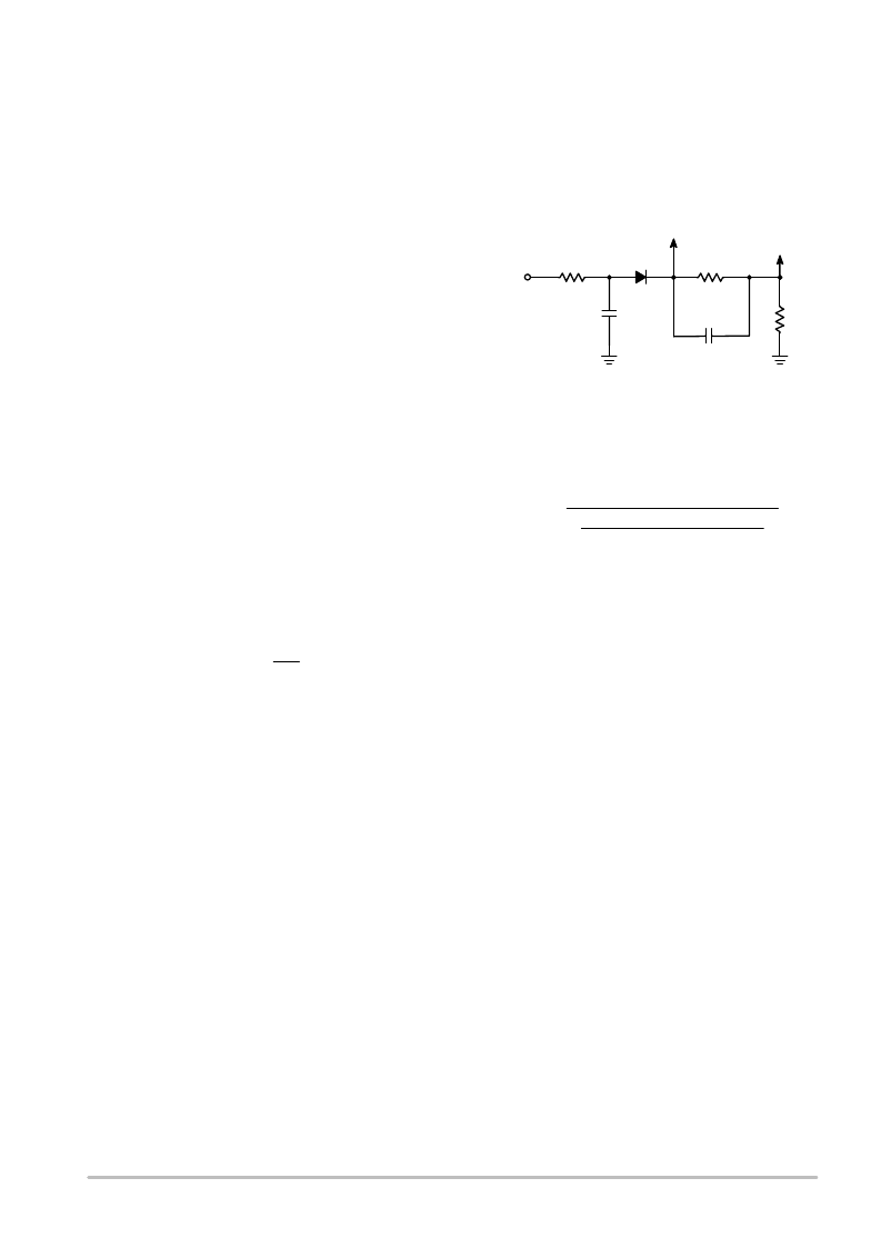
White LED Driver
The NCP1406 can be used as a constant current LED
driver which can drive up to 6 white LEDs in series as
shown in Figure 57. The LED current can be set by the
resistance value of R
S
. The desired LED current can be
calculated by the equation below:
ILED
1.19
RS
Moreover, the brightness of the LEDs can be adjusted by
a DC voltage or a PWM signal with an additional circuit
illustrated below:
DC/
PWM
Signal
R2
R1
100 k
C2
680 pF
GND
C1
0.1 F
D2
To FB Pin
To LED
Figure 45.
RS
With this additional circuit, the maximum LED current
is set by the above equation. The value of R2 can be
obtained by the following equation:
R2
VMAX
(ILED(MAX)
DCTL(MAX)
VD
1.19
RS
ILED(MIN))
R1
V
MAX
is the maximum voltage of the control signal,
D
CTL(MAX)
is the maximum duty cycle of the control signal,
V
D
is the diode forward voltage, I
LED(MAX)
is the maximum
LED current and I
LED(MIN)
is the minimum LED current. If
a PWM control signal is used, the signal frequency can be
in the range of 5.0 kHz to 30 kHz. It is recommended to
keep the input PWM frequency about 15 kHz to avoid
generating audio noise.
相關PDF資料 |
PDF描述 |
|---|---|
| NCP1410DMR2 | 250 mA Sync-Rect PFM Step-Up DC-DC Converter with Low-Battery Detector |
| NCP1410 | 250 mA Sync-Rect PFM Step-Up DC-DC Converter with Low-Battery Detector |
| NCP1411DMR2 | Sync-Rect PFM Step-Up DC-DC Converter with Low-Battery Detector and Ring-Killer |
| NCP1411D | Sync-Rect PFM Step-Up DC-DC Converter with Low-Battery Detector and Ring-Killer |
| NCP1411DMR2G | Sync-Rect PFM Step-Up DC-DC Converter with Low-Battery Detector and Ring-Killer |
相關代理商/技術參數 |
參數描述 |
|---|---|
| NCP1406V15GEVB | 功能描述:電源管理IC開發工具 NCP1406 EVAL BRD RoHS:否 制造商:Maxim Integrated 產品:Evaluation Kits 類型:Battery Management 工具用于評估:MAX17710GB 輸入電壓: 輸出電壓:1.8 V |
| NCP1406V25GEVB | 功能描述:電源管理IC開發工具 NCP1406 EVAL BRD RoHS:否 制造商:Maxim Integrated 產品:Evaluation Kits 類型:Battery Management 工具用于評估:MAX17710GB 輸入電壓: 輸出電壓:1.8 V |
| NCP1410DMR2 | 功能描述:直流/直流開關轉換器 ANA DC-DC CONVERTER RoHS:否 制造商:STMicroelectronics 最大輸入電壓:4.5 V 開關頻率:1.5 MHz 輸出電壓:4.6 V 輸出電流:250 mA 輸出端數量:2 最大工作溫度:+ 85 C 安裝風格:SMD/SMT |
| NCP1410DMR2G | 功能描述:直流/直流開關轉換器 ANA DC-DC CONVERTER RoHS:否 制造商:STMicroelectronics 最大輸入電壓:4.5 V 開關頻率:1.5 MHz 輸出電壓:4.6 V 輸出電流:250 mA 輸出端數量:2 最大工作溫度:+ 85 C 安裝風格:SMD/SMT |
| NCP1410GEVB | 功能描述:電源管理IC開發工具 NCP1410 EVAL BRD RoHS:否 制造商:Maxim Integrated 產品:Evaluation Kits 類型:Battery Management 工具用于評估:MAX17710GB 輸入電壓: 輸出電壓:1.8 V |
發布緊急采購,3分鐘左右您將得到回復。