- 您現在的位置:買賣IC網 > PDF目錄382380 > PCD5013 (NXP Semiconductors N.V.) FLEX roaming decoder II PDF資料下載
參數資料
| 型號: | PCD5013 |
| 廠商: | NXP Semiconductors N.V. |
| 英文描述: | FLEX roaming decoder II |
| 中文描述: | FleX創建漫游解碼器二 |
| 文件頁數: | 18/76頁 |
| 文件大小: | 270K |
| 代理商: | PCD5013 |
第1頁第2頁第3頁第4頁第5頁第6頁第7頁第8頁第9頁第10頁第11頁第12頁第13頁第14頁第15頁第16頁第17頁當前第18頁第19頁第20頁第21頁第22頁第23頁第24頁第25頁第26頁第27頁第28頁第29頁第30頁第31頁第32頁第33頁第34頁第35頁第36頁第37頁第38頁第39頁第40頁第41頁第42頁第43頁第44頁第45頁第46頁第47頁第48頁第49頁第50頁第51頁第52頁第53頁第54頁第55頁第56頁第57頁第58頁第59頁第60頁第61頁第62頁第63頁第64頁第65頁第66頁第67頁第68頁第69頁第70頁第71頁第72頁第73頁第74頁第75頁第76頁
1999 Apr 12
18
Philips Semiconductors
Product specification
FLEX
roaming decoder II
PCD5013
8.4.4
C
ONFIGURATION PACKET
(ID = 01H)
The configuration packet defines a number of different
configuration options for the PCD5013. The PCD5013
ignores this packet when decoding is enabled,
i.e. the ON bit in the control packet is set (Table 12).
DFC:
disable fractional clock (Table 8). When this bit is set
and IDE is set, the CLKOUT signal generates a 40 kHz
signal (EXTAL divided-by-4). When this bit is cleared and
IDE is set, the CLKOUT signal generates a 38.4 kHz signal
(EXTAL fractionally divided by
25
6
). This bit has no effect
when IDE is cleared. Value after reset = 0.
IDE:
internal demodulator enable (Table 8). When this bit
is set, the internal demodulator is enabled and the clock
frequency at EXTAL is expected to be 160 kHz. When this
bit is cleared, the internal demodulator is disabled and the
clock frequency at EXTAL is expected to be 76.8 kHz.
Value after reset = 0.
OFD:
oscillator frequency difference (Tables 4 and 8).
These bits represent the maximum frequency difference
between the 76.8 kHz oscillator (accounting for ageing,
temperature variation, manufacturing tolerance etc.) and
the worst case transmitter bit rate (specified as
±
25 parts
per million (ppm) in the FLEX
specification).
For example, if the transmitter tolerance is
±
25 ppm and
the 76.8 kHz oscillator tolerance is
±
140 ppm, the
transmitter-oscillator frequency difference is
±
165 ppm
and OFD should be cleared (300 ppm maximum). Value
after reset = 0. Note that configuring a smaller frequency
difference in this packet results in lower power
consumption due to higher receiver battery save ratios.
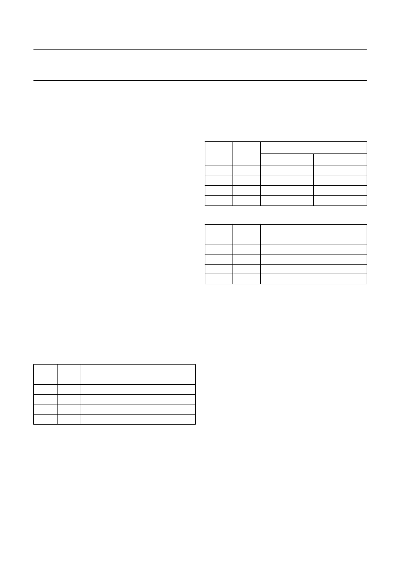
Table 4
Oscillator frequency difference
PCE:
partial correlation enable (Table 8). When this bit is
set, partial correlation of addresses is enabled. When
partial correlation is enabled, the PCD5013 shuts down
the receiver before the end of the last FLEX
block which
contains addresses if it can determine that none of the
addresses in that FLEX
block matches any enabled
address in the PCD5013. When this bit is cleared, the
receiver is controlled as in the PCD5008. Value after
reset = 0.
OFD
1
OFD
0
FREQUENCY DIFFERENCE
(ppm)
±
300
±
150
±
75
±
0
0
0
1
1
0
1
0
1
SP:
signal polarity (Tables 8, 5 and 6). These bits set the
polarity of EXTS1 and EXTS0 input signals. The polarity of
the EXTS1 and EXTS0 bits is determined by the receiver
design. Value after reset = 0.
Table 5
Input signal polarity
Table 6
FLEX
4 level FSK modulation (SP = 00)
SME:
synchronous mode enable (Table 8). When this bit
is set, a status packet is sent automatically whenever the
synchronous mode update (SMU) bit in the status packet
is set. This happens whenever a change occurs in the
synchronous mode (SM) status bit, which indicates that
the decoder is synchronized to a FLEX
data stream.
The host can use the SM bit in the status packet as an
in-range/out-of-range indication. Value after reset = 0.
COD:
clock output disable (Table 8). When this bit is
cleared, a 38.4 or 40 kHz signal is output on the
CLKOUT pin (depending on the values of IDE and DFC).
When this bit is set, the CLKOUT pin is driven LOW. Value
after reset = 0.
Setting and clearing this bit can cause pulses on the
CLKOUT pin that are less than one half the 38.4 kHz
period.
When the clock output is enabled and not set for
intermittent operation (see ICO in this packet), the
CLKOUT pin always outputs the clock signal even when
the PCD5013 is in reset (as long as a clock signal is
available to the PCD5013 oscillator).
When the PCD5013 is used in internal demodulator
mode (i.e. uses a 160 kHz oscillator), the CLKOUT pin
is 80 kHz from reset until the time the IDE bit is set.
SP
1
SP
0
SIGNAL POLARITY
EXTS1
EXTS0
0
0
1
1
0
1
0
1
normal
normal
inverted
inverted
normal
inverted
normal
inverted
EXTS1
EXTS0
DEVIATION
(Hz)
1
1
0
0
0
1
1
0
+4800
+1600
1600
4800
相關PDF資料 |
PDF描述 |
|---|---|
| PCD5013H | FLEX roaming decoder II |
| PCD5032 | ADPCM CODEC for digital cordless telephones |
| PCD5032H | ADPCM CODEC for digital cordless telephones |
| PCD5032T | ADPCM CODEC for digital cordless telephones |
| PCD5041 | DECT burst mode controller |
相關代理商/技術參數 |
參數描述 |
|---|---|
| PCD5013H | 制造商:PHILIPS 制造商全稱:NXP Semiconductors 功能描述:FLEX roaming decoder II |
| PCD5032 | 制造商:PHILIPS 制造商全稱:NXP Semiconductors 功能描述:ADPCM CODEC for digital cordless telephones |
| PCD5032B | 制造商:未知廠家 制造商全稱:未知廠家 功能描述:Linear CODEC |
| PCD5032D | 制造商:未知廠家 制造商全稱:未知廠家 功能描述:Linear CODEC |
| PCD5032H | 制造商:PHILIPS 制造商全稱:NXP Semiconductors 功能描述:ADPCM CODEC for digital cordless telephones |
發布緊急采購,3分鐘左右您將得到回復。