- 您現在的位置:買賣IC網 > PDF目錄361259 > QEB125-48S05 (Electronic Theatre Controls, Inc.) SINGLE OUTPUT PDF資料下載
參數資料
| 型號: | QEB125-48S05 |
| 廠商: | Electronic Theatre Controls, Inc. |
| 英文描述: | SINGLE OUTPUT |
| 中文描述: | 單輸出 |
| 文件頁數: | 2/2頁 |
| 文件大小: | 105K |
| 代理商: | QEB125-48S05 |
Model
Number
Input
Range
Output
Voltage
Output
Current
Eff
(6)
(%)
Load
regulation
QEB125-48S1P8
QEB125-48S2P5
QEB125-48S3P3
QEB125-48S05
36 – 75 VDC
36 – 75 VDC
36 – 75 VDC
36 – 75 VDC
1.8 VDC
2.5 VDC
3.3 VDC
5 VDC
35A
35A
30A
25A
84
86
88
90
5.4mV
7.5mV
10mV
15mV
PRODUCT OPTIONS TABLE
Option
Suffix
Negative remote ON/OFF logic, 0.20” pin length (standard)
-
Negative remote ON/OFF logic, 0.145” pin length
-L
Negative remote ON/OFF logic, 0.11” pin length
-K
Positive remote ON/OFF logic, 0.20” pin length
-P
Positive remote ON/OFF logic, 0.145” pin length
-S
Positive remote ON/OFF logic, 0.11” pin length
-M
Note
1.
Maximum output deviation is 10% inclusive of trim. If remote sense is not being used, the +V sense should be connected to its corresponding
+OUTPUT and likewise the –sense should be connected to its corresponding –OUTPUT.
An external filter capacitor is required for normal operation. The capacitor should be capable of handing 1A ripple current for 48V models. Power mate
suggest: Nippon chemi-con KMF series, 220 F/100V, ESR 90m .
The negative / positive logic and pin length are optional ( see table ). The pin voltage is referenced to negative input.
Heat sink is optional and P/N
7G-0029
7G-0030
7G-0031
7G-0032.
The QEB125 meets level A and level B conducted emissions only with external components connected before the input pin to the converter.
Typical value at nominal input voltage and full load
BASEPLATE GROUNGING
Base-plate should be grounded at one of the four screw bolts prior to operation.
The converter is provided by basic insulation.
2.
3.
4.
5.
6.
7.
8.
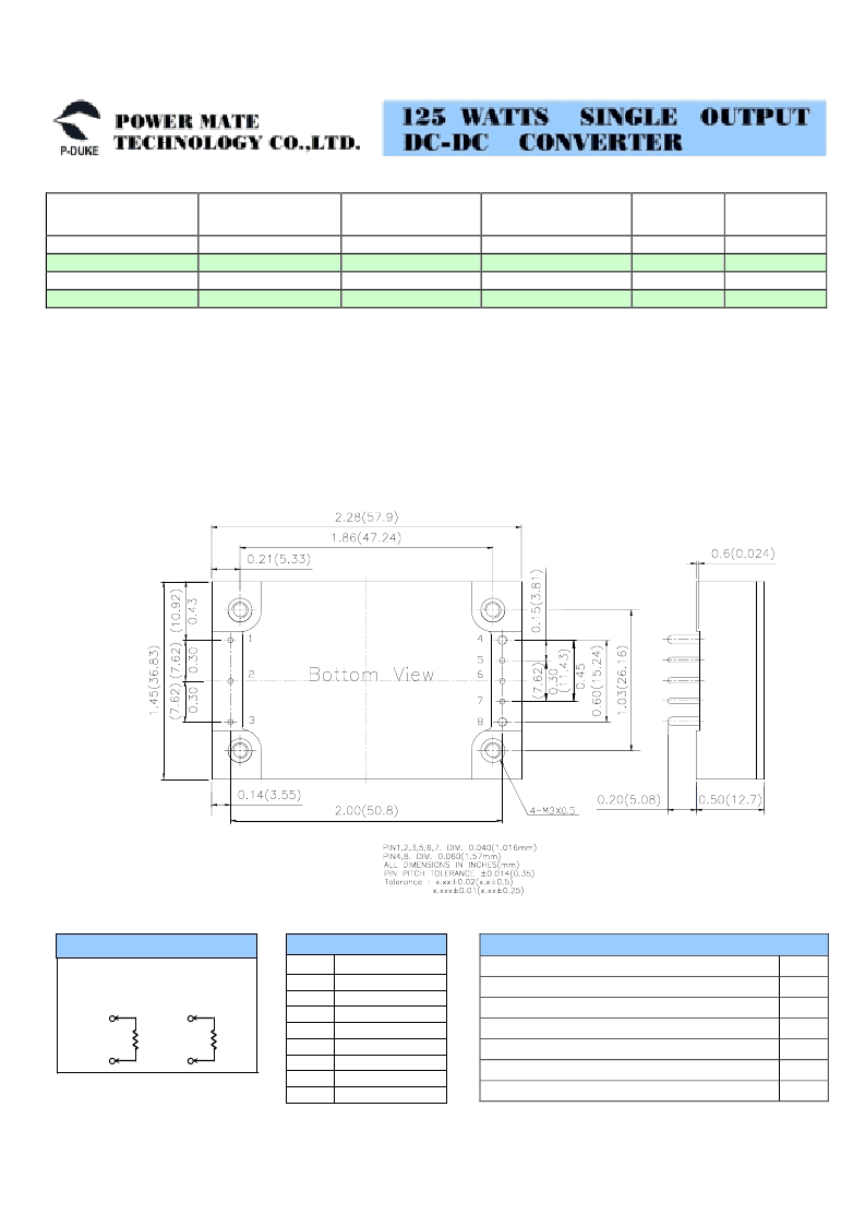
PIN
1
2
3
4
5
6
7
8
Define
- INPUT
ON/OFF
+ INPUT
- OUTPUT
- SENSE
TRIM
+ SENSE
+ OUTPUT
PIN CONNECTION
Output can be externally trimmed by
using the method shown below.
EXTERNAL OUTPUT TRIMMING
7
6
TRIM UP
R
U
6
5
TRIM DOWN
R
D
Example
QEB125-48S3P3-P
(7)
相關PDF資料 |
PDF描述 |
|---|---|
| QEB125-48S1P8 | SINGLE OUTPUT |
| QEB125-48S2P5 | SINGLE OUTPUT |
| QEB125-48S3P3 | SINGLE OUTPUT |
| QEB363 | SUBMINIATURE PLASTIC INFRARED EMITTING DIODE |
| QEB373 | SUBMINIATURE PLASTIC INFRARED EMITTING DIODE |
相關代理商/技術參數 |
參數描述 |
|---|---|
| QEB125-48S12 | 制造商:P-DUKE 制造商全稱:Power Mate Technology Co., LTD 功能描述:125 WATTS MAXIMUM OUTPUT POWER |
| QEB125-48S15 | 制造商:P-DUKE 制造商全稱:Power Mate Technology Co., LTD 功能描述:125 WATTS MAXIMUM OUTPUT POWER |
| QEB125-48S1P8 | 制造商:未知廠家 制造商全稱:未知廠家 功能描述:SINGLE OUTPUT |
| QEB125-48S2P5 | 制造商:未知廠家 制造商全稱:未知廠家 功能描述:SINGLE OUTPUT |
| QEB125-48S3P3 | 制造商:未知廠家 制造商全稱:未知廠家 功能描述:SINGLE OUTPUT |
發布緊急采購,3分鐘左右您將得到回復。