- 您現(xiàn)在的位置:買賣IC網(wǎng) > Datasheet目錄46 > QPI-8LZ-01 (Vicor Corporation)IC HOT SWAP EMI FILTER 16LGA Datasheet資料下載
參數(shù)資料
| 型號: | QPI-8LZ-01 |
| 廠商: | Vicor Corporation |
| 文件頁數(shù): | 7/17頁 |
| 文件大小: | 1498K |
| 描述: | IC HOT SWAP EMI FILTER 16LGA |
| 標準包裝: | 20 |
| 系列: | Picor®, QUIETPOWER® |
| 類型: | 熱交換開關(guān) |
| 應(yīng)用: | AdvancedTCA |
| 內(nèi)部開關(guān): | 是 |
| 電流限制: | 6A |
| 電源電壓: | 36 V ~ 76 V |
| 工作溫度: | -40°C ~ 125°C |
| 安裝類型: | 表面貼裝 |
| 封裝/外殼: | * |
| 供應(yīng)商設(shè)備封裝: | * |
| 包裝: | 管件 |
| 其它名稱: | 1102-1092-5 |
C
E
Picor Corporation ?picorpower.com
QPI-8
Rev 1.5, Page 7 of 17
QPI-8
QUIETPOWER
?/DIV>
once again satisfied the QPI-8 then will require ~16ms to
restart and turn the pass FET back on, charging the bulk
capacitance. The PWRGD signal will be low during the whole
time of the transient, the 16ms delay and the time required
to restore the BUS voltage across the bulk capacitors. See
Figure 18 for a detailed description of the under and over
voltage fault event timings.
The ATCA guidelines have a 5ms, zero-volt bus transient
requirement that must be met. The circuit in Figure 13 shows
that with the addition of a series diode (D), resistor (RUVEN)
and a capacitor (CE), the UVEN pin can be filtered from
reacting immediately to a transient loss of power, thereby
maintaining a high PWRGD status and allowing the converter
to run off of its bulk capacitors.
There is a practical limit to the amount of bulk capacitance
that can be used as an energy source during a low voltage bus
transient event. Upon recovery from the transient, the QPI-8
has to supply the current to charge the capacitors back to the
BUS+ voltage value and provide the current for the converter
in less time that the fault delay, about 1.2ms. If the caps
cannot be completely charged prior to the fault time-out,
then the QPI-8 will shut off its pass FET, assert the PWRGD
pin low, and then retry about 95ms later.
For example:
A system with a bus voltage of 48V and a 4A bus
current has a drop in the bus voltage to 40V and then quickly
recovers back to 48V. While at 40V the bus current increases
to 4.8A to maintain the output load. To restore the bulk
capacitor back to the 48V bus voltage the amount of bus
current available, limited by the QPI-8s current limit of 12A,
will be the 12A minus the average converter load current
(4.4A). Without regard to tolerances, the equation to
calculate the maximum amount of capacitance that can be
charged within the 12A pulse period (1.2ms) is:
Where I = 4.4A
攖 = 1.2ms
擵 = 8V
The value of the bulk capacitor is 1140礔; to maintain some
margin for capacitor tolerance a 1000uF capacitor or smaller
should be used.
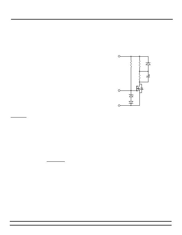
Another option is to use a current limiting charge circuit to
restore the capacitors. In Figure 14, the bulk storage
capacitor (CHOLD-UP) is charged through RC after PWRGD
has been released from its active low state and QHOLD-UP is
allowed to turn on. The time it takes for CHOLD-UP to charge
up to the bus supply voltage is dependent on the value of RC
and CHOLD-UP. If the bus supply were to be removed, the
energy stored in CHOLD-UP will be released through the
diode D and the QHOLD-UP FET, which will conduct either by
being actively turned on by PWRGD or through its body
diode. Once the bus voltage is restored, CHOLD-UP will start
to re-charge back to the bus supply voltage.
Figure 14 - Powergood controlled, auxiliary bulk storage
capacitor charging circuit.
The amount of capacitance required can be determined using
the following equation:
Where: E = Hold-up energy
V
BUS
= BUS supply voltage
V
UVLO
= converters UVLO limit
The 15V zener and 100V diodes are used to protect the FETs
gate to source maximum voltage limit and to protect the QPI-
8s PWRGD pin. At start-up, the voltage on QPI- is equal to
BUS+ with respect to BUS-. If the 100V diode were not
present, then the PWRGD pin would be pulled up to the BUS+
voltage minus the diode drop of zener. At start-up, the
PWRGD pin is in an active low state and will get damaged
being forced to the BUS+ voltage. The zener diode protects
against the FETs maximum gate to source voltage being
exceeded.
The alternative to adding large amounts of bulk capacitors to
the converters input is to create a voltage supply greater
than that of the bus supply. This takes advantage of the
increased stored energy of a capacitor at higher voltages.
相關(guān)PDF資料 |
PDF描述 |
|---|---|
| SA56004HD,118 | IC TEMP SENSOR DIGITAL 8SOIC |
| SC2463TSTRT | IC REG QD BCK/LINEAR 28TSSOP |
| SC338AIMSTRT | IC REG CTRLR DUAL POS ADJ 10MSOP |
| SC402BMLTRT | IC REG DL BCK/LINEAR SYNC 32MLPQ |
| SC403MLTRT | IC REG DL BCK/LINEAR SYNC 32MLPQ |
相關(guān)代理商/技術(shù)參數(shù) |
參數(shù)描述 |
|---|---|
| QPI-9 | 制造商:VICOR 制造商全稱:Vicor Corporation 功能描述:Hot-Swap SiP With VI Chip EMI Filter |
| QPI-9-CB1 | 制造商:Vicor Corporation 功能描述:QPI-9LZ Filter w/ Hot-Swap Carrier Board for 24 V VI Chip "-CB" Boards up to 6A |
| QPI-9L | 制造商:VICOR 制造商全稱:Vicor Corporation 功能描述:VI Chip Input EMI Filters |
| QPI-9LZ | 制造商:VICOR 制造商全稱:Vicor Corporation 功能描述:Hot-Swap SiP With VI Chip EMI Filter |
| QPI-9LZ-01 | 制造商:VICOR 制造商全稱:Vicor Corporation 功能描述:Hot-Swap SiP With VI Chip EMI Filter |
發(fā)布緊急采購,3分鐘左右您將得到回復(fù)。