- 您現在的位置:買賣IC網 > PDF目錄98270 > TPA2011D1YFFT (TEXAS INSTRUMENTS INC) 3.24 W, 1 CHANNEL, AUDIO AMPLIFIER, BGA9 PDF資料下載
參數資料
| 型號: | TPA2011D1YFFT |
| 廠商: | TEXAS INSTRUMENTS INC |
| 元件分類: | 音頻/視頻放大 |
| 英文描述: | 3.24 W, 1 CHANNEL, AUDIO AMPLIFIER, BGA9 |
| 封裝: | 1.21 X 1.16 MM, 0.40 MM PITCH, GREEN, PLASTIC, DSBGA-9 |
| 文件頁數: | 4/24頁 |
| 文件大小: | 670K |
| 代理商: | TPA2011D1YFFT |
fc +
1
2p R
I
C
I
C
I +
1
2p R
I
fc
_
+
IN
IN+
PWM
H
Bridge
VO+
VO
Internal
Oscillator
CS
ToBattery
VDD
GND
Bias
Circuitry
Differential
Input
TPA2011D1
Filter-FreeClassD
EN
R
I
R
I
+
SLOS626A – DECEMBER 2009 – REVISED MAY 2010
www.ti.com
and the capacitor can cause a loss in efficiency. For filtering lower-frequency noise signals, a 10 mF or greater
capacitor (CS2) placed near the audio power amplifier would also help, but it is not required in most applications
because of the high PSRR of this device. Typically, the smaller the capacitor's case size, the lower the
inductance and the closer it can be placed to the TPA2011D1. X5R and X7R dielectric capacitors are
recommended for both CS1 and CS2.
Input Capacitors (CI)
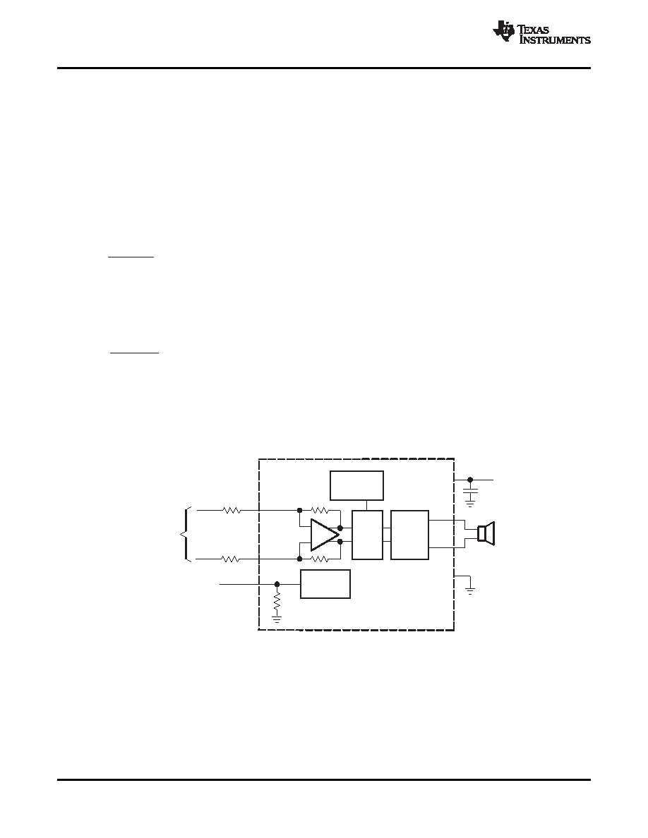
The TPA2011D1 does not require input coupling capacitors if the design uses a differential source that is biased
from 0.5 V to VDD –0.8 V (shown in Figure 28). If the input signal is not biased within the recommended
common-mode input range, if needing to use the input as a high pass filter (shown in Figure 29), or if using a
single-ended source (shown in Figure 30), input coupling capacitors are required.
The input capacitors and input resistors form a high-pass filter with the corner frequency, fc, determined in
(2)
The value of the input capacitor is important to consider as it directly affects the bass (low frequency)
performance of the circuit. Speakers in wireless phones cannot usually respond well to low frequencies, so the
corner frequency can be set to block low frequencies in this application.
Equation 3 is reconfigured to solve for the input coupling capacitance.
(3)
If the corner frequency is within the audio band, the capacitors should have a tolerance of ±10% or better,
because any mismatch in capacitance causes an impedance mismatch at the corner frequency and below.
For a flat low-frequency response, use large input coupling capacitors (1 mF). However, in a GSM phone the
ground signal is fluctuating at 217 Hz, but the signal from the codec does not have the same 217 Hz fluctuation.
The difference between the two signals is amplified, sent to the speaker, and heard as a 217 Hz hum.
Figure 28. Typical TPA2011D1 Application Schematic With Differential Input for a Wireless Phone
12
Copyright 2009–2010, Texas Instruments Incorporated
Product Folder Link(s) :TPA2011D1
相關PDF資料 |
PDF描述 |
|---|---|
| TPA2012D2RTJ | 2.1 W, 2 CHANNEL, AUDIO AMPLIFIER, PQCC20 |
| TPA2012D2YZH | 2.1 W, 2 CHANNEL, AUDIO AMPLIFIER, BGA16 |
| TPA2012D2RTJRG4 | 2.1 W, 2 CHANNEL, AUDIO AMPLIFIER, PQCC20 |
| TPA2012D2RTJR | 2.1 W, 2 CHANNEL, AUDIO AMPLIFIER, PQCC20 |
| TPA2012D2RTJTG4 | 2.1 W, 2 CHANNEL, AUDIO AMPLIFIER, PQCC20 |
相關代理商/技術參數 |
參數描述 |
|---|---|
| TPA2012D2 | 制造商:TI 制造商全稱:Texas Instruments 功能描述:2.1 W/CH STEREO FILTER-FREE CLASS-D AUDIO POWER AMPLIFIER |
| TPA2012D2_07 | 制造商:TI 制造商全稱:Texas Instruments 功能描述:2.1 W/CH STEREO FILTER-FREE CLASS-D AUDIO POWER AMPLIFIER |
| TPA2012D2EVM | 功能描述:音頻 IC 開發工具 TPA2012D2 Eval Mod RoHS:否 制造商:Texas Instruments 產品:Evaluation Kits 類型:Audio Amplifiers 工具用于評估:TAS5614L 工作電源電壓:12 V to 38 V |
| TPA2012D2PWP | 制造商:Texas Instruments 功能描述: |
| TPA2012D2PWPR | 制造商:Texas Instruments 功能描述: |
發布緊急采購,3分鐘左右您將得到回復。