- 您現在的位置:買賣IC網 > PDF目錄98282 > TPS5420MDREP (TEXAS INSTRUMENTS INC) 5.2 A SWITCHING REGULATOR, 600 kHz SWITCHING FREQ-MAX, PDSO8 PDF資料下載
參數資料
| 型號: | TPS5420MDREP |
| 廠商: | TEXAS INSTRUMENTS INC |
| 元件分類: | 穩壓器 |
| 英文描述: | 5.2 A SWITCHING REGULATOR, 600 kHz SWITCHING FREQ-MAX, PDSO8 |
| 封裝: | GREEN, PLASTIC, MS-012AA, SOIC-8 |
| 文件頁數: | 6/23頁 |
| 文件大小: | 658K |
| 代理商: | TPS5420MDREP |
www.ti.com
R2 +
R1
1.221
V
OUT *
1.221
(12)
+
10V-21V
L1
27 H
m
GND
VSNS
NC
ENA
BOOT
PH
D1
B340A
C2
0.01 F
m
R2
3.24kW
R1
10kW
VIN
C1
10 F
m
U1
TPS5420D
TP5
5V
7
1
5
8
2
4
3
6
VOUT
VIN
ENA
C3
100 F
m
(SeeNote A)
SLVS717 – DECEMBER 2006
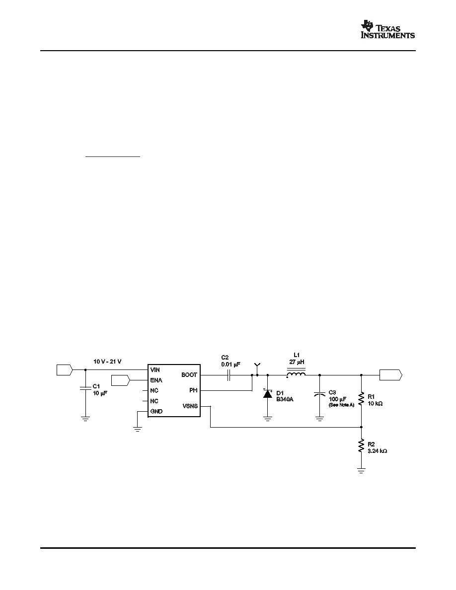
For this design example, a single 100-
F output capacitor is chosen for C3. The calculated RMS ripple current is
143 mA, and the maximum ESR required is 88 m
. A capacitor that meets these requirements is an AVX
TPSD107M010R0080, rated at 10 V, with a maximum ESR of 80 m
and a ripple current rating of 1.369 A. This
capacitor results in a peak-to-peak output ripple of 26 mV using Equation 10. An additional small 0.1-
F ceramic
bypass capacitor may also used, but is not included in this design.
Other capacitor types can be used with the TPS5420, depending on the needs of the application.
Output Voltage Setpoint
The output voltage of the TPS5420 is set by a resistor divider (R1 and R2) from the output to the VSENSE pin.
Calculate the R2 resistor value for the output voltage of 5 V using Equation 12:
For any TPS5420 design, start with an R1 value of 10 k
. R2 is then 3.24 k.
Boot Capacitor
The boot capacitor should be 0.01
F.
Catch Diode
The TPS5420 is designed to operate using an external catch diode between PH and GND. The selected diode
must meet the absolute maximum ratings for the application—reverse voltage must be higher than the maximum
voltage at the PH pin, which is VINMAX + 0.5 V. Peak current must be greater than IOUTMAX plus one-half the
peak-to-peak inductor current. Forward voltage drop should be small for higher efficiencies. It is important to
note that the catch diode conduction time is typically longer than the high-side FET on time; therefore, the diode
parameters improve the overall efficiency. Additionally, check that the device chosen is capable of dissipating
the power losses. For this design, a Diodes, Inc. B340A is chosen, with a reverse voltage of 40 V, forward
current of 3 A, and a forward voltage drop of 0.5 V.
Additional Circuits
Figure 12 shows an application circuit using a wide input voltage range. The design parameters are similar to
those given for the design example, with a larger-value output inductor and a lower closed-loop crossover
frequency.
A.
C3 = Tantalum AVX TPSD107M010R0080
Figure 12. 10-V — 21-V Input to 5-V Output Application Circuit
14
相關PDF資料 |
PDF描述 |
|---|---|
| TPS54225PWP | 4.5 A SWITCHING REGULATOR, 700 kHz SWITCHING FREQ-MAX, PDSO14 |
| TPS54225PWPR | 4.5 A SWITCHING REGULATOR, 700 kHz SWITCHING FREQ-MAX, PDSO14 |
| TPS54225TPWPRQ1 | SWITCHING REGULATOR, PDSO14 |
| TPS54226PW | |
| TPS54227DDA | 4.7 A SWITCHING REGULATOR, 700 kHz SWITCHING FREQ-MAX, PDSO8 |
相關代理商/技術參數 |
參數描述 |
|---|---|
| TPS5420MDREPG4 | 功能描述:直流/直流開關調節器 EP 2A Wide-Inp-Range StepDwn SWIFT Cnvrtr RoHS:否 制造商:International Rectifier 最大輸入電壓:21 V 開關頻率:1.5 MHz 輸出電壓:0.5 V to 0.86 V 輸出電流:4 A 輸出端數量: 最大工作溫度: 安裝風格:SMD/SMT 封裝 / 箱體:PQFN 4 x 5 |
| TPS5420-Q1 | 制造商:TI 制造商全稱:Texas Instruments 功能描述:2-A WIDE-INPUT-RANGE STEP-DOWN SWIFTa?¢ CONVERTER |
| TPS5420QDRQ1 | 功能描述:直流/直流開關調節器 2A Wide-Input-Range Step-Down Converter RoHS:否 制造商:International Rectifier 最大輸入電壓:21 V 開關頻率:1.5 MHz 輸出電壓:0.5 V to 0.86 V 輸出電流:4 A 輸出端數量: 最大工作溫度: 安裝風格:SMD/SMT 封裝 / 箱體:PQFN 4 x 5 |
| TPS54218 | 制造商:TI 制造商全稱:Texas Instruments 功能描述:2.95 V to 6 V Input 2 A Output 2MHz Synchronous Step Down Switcher With Integrated FETs (SWIFT) |
| TPS54218_12 | 制造商:TI 制造商全稱:Texas Instruments 功能描述:2.95 V to 6 V Input, 2 A Output, 2MHz, Synchronous Step Down |
發布緊急采購,3分鐘左右您將得到回復。