- 您現(xiàn)在的位置:買賣IC網(wǎng) > PDF目錄373923 > AD7885AN (ANALOG DEVICES INC) LC2MOS 16-Bit, High Speed Sampling ADCs PDF資料下載
參數(shù)資料
| 型號: | AD7885AN |
| 廠商: | ANALOG DEVICES INC |
| 元件分類: | ADC |
| 英文描述: | LC2MOS 16-Bit, High Speed Sampling ADCs |
| 中文描述: | 1-CH 16-BIT FLASH METHOD ADC, PARALLEL ACCESS, PDIP28 |
| 封裝: | PLASTIC, DIP-28 |
| 文件頁數(shù): | 11/16頁 |
| 文件大小: | 319K |
| 代理商: | AD7885AN |
AD7884/AD7885
REV. C
–11–
If the noise in the converter is too high for an application, it can
be reduced by oversampling and digital filtering. T his involves
sampling the input at higher than the required word rate and
then averaging to arrive at the final result. T he very fast conver-
sion time of the AD7884/AD7885 makes it very suitable for
oversampling. For example, if the required input bandwidth is
40 kHz, the AD7884/AD7885 could be oversampled by a factor
of 2. T his yields a 3 dB improvement in the effective SNR per-
formance. T he noise performance in the
±
5 volt input range is
now effectively 85
μ
V rms and the resultant spread of codes for
2500 conversions will be four. T his is shown in Figure 15.
1500
0
1000
500
C
(X – 1)
(X)
(X + 1) (X + 2)
CODE
Figure 15. Histogram of 2500 Conversions of a DC Input
Using a
×
2 Oversampling Ratio
Dynamic Performance
With a combined conversion and acquisition time of 6
μ
s, the
AD7884/AD7885 is ideal for wide bandwidth signal processing
applications. Signal to (Noise + Distortion), T otal Harmonic
Distortion, Peak Harmonic or Spurious Noise and Intermodula-
tion Distortion are all specified. Figure 16 shows a typical
FFT plot of a 1.8 kHz,
±
5 V input after being digitized by the
AD7884/AD7885.
0
–150
–60
–120
–90
–30
2048 POINT FFT
d
f = 1.8kHz,
±
5V SINE WAVE
f = 163kHz
SNR = 87dB
THD = –95dB
Figure 16. AD7884/AD7885 FFT Plot
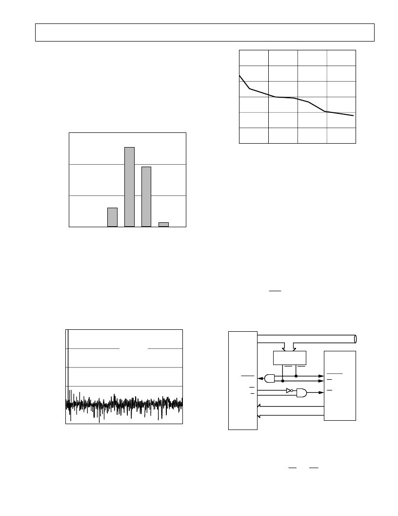
E ffective Number of Bits
T he formula for SNR (see T erminology section) is related to
the resolution or number of bits in the converter. Rewriting the
formula, below, gives a measure of performance expressed in
effective number of bits (N).
N
= (
SNR
– 1.76)/6.02
16
10
80
13
11
20
12
0
15
14
60
40
FREQUENCY – kHz
E
Figure 17. Effective Number of Bits vs. Frequency
T he effective number of bits for a device can be calculated from
its measured SNR. Figure 17 shows a typical plot of effective
number of bits versus frequency for the AD7884. T he sampling
frequency is 166 kHz.
MICROPROCE SSOR INT E RFACING
T he AD7884/AD7885 is designed on a high speed process
which results in very fast interfacing timing (Data Access T ime
of 57 ns max). T he AD7884 has a full 16-bit parallel bus, and
the AD7885 has an 8-bit wide bus. T he AD7884, with its paral-
lel interface, is suited to 16-bit parallel machines whereas the
AD7885, with its byte interface, is suited to 8-bit machines.
Some examples of typical interface configurations follow.
AD7884 to MC68000 Interface
Figure 18 shows a general interface diagram for the MC68000,
16-bit microprocessor to the AD7884. In Figure 18, conversion
is initiated by bringing
CSA
low (i.e., writing to the appropriate
address). T his allows the processor to maintain control over the
complete conversion process. In some cases it may be more
desirable to control conversion independent from the processor.
T his can be done by using an external sampling timer.
MC68000
AD7884
ADDRESS
DECODE LOGIC
CONVST
CS
RD
DB15 – DB0
R/W
DATA BUS
ADDRESS BUS
A23 – A1
D15 – D0
DTACK
AS
CSA
CSB
Figure 18. AD7884 to MC68000 Interface
Once conversion has been started, the processor must wait until
it is completed before reading the result. T here are two ways of
ensuring this. T he first way is to simply use a software delay to
wait for 6.5
μ
s before bringing
CS
and
RD
low to read the data.
相關(guān)PDF資料 |
PDF描述 |
|---|---|
| AD7885BN | LC2MOS 16-Bit, High Speed Sampling ADCs |
| AD7886JP | LC2MOS 12-Bit, 750 kHz/1 MHz, Sampling ADC |
| AD7886 | LC2MOS 12-Bit, 750 kHz/1 MHz, Sampling ADC |
| AD7886BD | LC2MOS 12-Bit, 750 kHz/1 MHz, Sampling ADC |
| AD7886KD | LC2MOS 12-Bit, 750 kHz/1 MHz, Sampling ADC |
相關(guān)代理商/技術(shù)參數(shù) |
參數(shù)描述 |
|---|---|
| AD7885AQ | 制造商:Analog Devices 功能描述: 制造商:Analog Devices 功能描述:IC 16-BIT ADC |
| AD7885BQ | 制造商:Analog Devices 功能描述: |
| AD7885JQ | 制造商:Analog Devices 功能描述: 制造商:Rochester Electronics LLC 功能描述: |
| AD7886JD | 功能描述:IC ADC 12BIT SAMPLING HS 28-CDIP RoHS:否 類別:集成電路 (IC) >> 數(shù)據(jù)采集 - 模數(shù)轉(zhuǎn)換器 系列:- 產(chǎn)品培訓(xùn)模塊:Lead (SnPb) Finish for COTS Obsolescence Mitigation Program 標(biāo)準(zhǔn)包裝:250 系列:- 位數(shù):12 采樣率(每秒):1.8M 數(shù)據(jù)接口:并聯(lián) 轉(zhuǎn)換器數(shù)目:1 功率耗散(最大):1.82W 電壓電源:模擬和數(shù)字 工作溫度:-40°C ~ 85°C 安裝類型:表面貼裝 封裝/外殼:48-LQFP 供應(yīng)商設(shè)備封裝:48-LQFP(7x7) 包裝:管件 輸入數(shù)目和類型:2 個單端,單極 |
| AD7886JP | 功能描述:IC ADC 12BIT SAMPLING HS 28-PLCC RoHS:否 類別:集成電路 (IC) >> 數(shù)據(jù)采集 - 模數(shù)轉(zhuǎn)換器 系列:- 標(biāo)準(zhǔn)包裝:1 系列:- 位數(shù):14 采樣率(每秒):83k 數(shù)據(jù)接口:串行,并聯(lián) 轉(zhuǎn)換器數(shù)目:1 功率耗散(最大):95mW 電壓電源:雙 ± 工作溫度:0°C ~ 70°C 安裝類型:通孔 封裝/外殼:28-DIP(0.600",15.24mm) 供應(yīng)商設(shè)備封裝:28-PDIP 包裝:管件 輸入數(shù)目和類型:1 個單端,雙極 |
發(fā)布緊急采購,3分鐘左右您將得到回復(fù)。