- 您現在的位置:買賣IC網 > PDF目錄373929 > AD8019ARU-REEL (ANALOG DEVICES INC) DSL Line Driver with Power-Down PDF資料下載
參數資料
| 型號: | AD8019ARU-REEL |
| 廠商: | ANALOG DEVICES INC |
| 元件分類: | 通用總線功能 |
| 英文描述: | DSL Line Driver with Power-Down |
| 中文描述: | DUAL LINE DRIVER, PDSO14 |
| 封裝: | TSSOP-14 |
| 文件頁數: | 1/20頁 |
| 文件大小: | 782K |
| 代理商: | AD8019ARU-REEL |
REV. 0
Information furnished by Analog Devices is believed to be accurate and
reliable. However, no responsibility is assumed by Analog Devices for its
use, nor for any infringements of patents or other rights of third parties that
may result from its use. No license is granted by implication or otherwise
under any patent or patent rights of Analog Devices.
a
AD8019
One Technology Way, P.O. Box 9106, Norwood, MA 02062-9106, U.S.A.
Tel: 781/329-4700
Fax: 781/326-8703
www.analog.com
Analog Devices, Inc., 2001
DSL Line Driver
with Power-Down
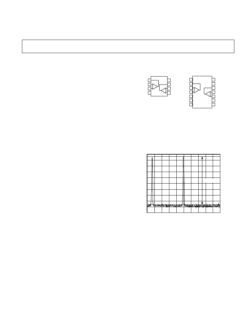
PIN CONFIGURATIONS
8
7
6
5
1
2
3
4
AD8019AR
–IN1
+IN1
–V
S
OUT1
OUT2
–IN2
+V
S
+IN2
14
13
12
11
10
9
8
1
2
3
4
5
6
7
AD8019ARU
NC = NO CONNECT
DGND
NC
PWDN
NC
NC
+V
S
NC
OUT1
–IN1
+IN1
–V
S
OUT2
–IN2
+IN2
FEATURES
Low Distortion, High Output Current Amplifiers
Operate from 12 V to 12 V Power Supplies,
Ideal for High-Performance ADSL CPE, and xDSL
Modems
Low Power Operation
9 mA/Amp (Typ) Supply Current
Digital (1-Bit) Power-Down
Voltage Feedback Amplifiers
Low Distortion
Out-of-Band SFDR –80 dBc @ 100 kHz into 100
High Speed
175 MHz Bandwidth (–3 dB), G = +1
400 V/ s Slew Rate
High Dynamic Range
V
OUT
to within 1.2 V of Power Supply
Line
APPLICATIONS
ADSL, VDSL, HDSL, and Proprietary xDSL USB, PCI,
PCMCIA Modems, and Customer Premise Equipment
(CPE)
PRODUCT DESCRIPTION
The AD8019 is a low cost xDSL line driver optimized to drive a
minimum of 13 dBm into a 100
load while delivering outstand-
ing distortion performance. The AD8019 is designed on a 24 V
high-speed bipolar process enabling the use of
±
12 V power
supplies or 12 V only. When operating from a single 12 V sup-
ply the highly efficient amplifier architecture can typically deliver
170 mA output current into low impedance loads through a
1:2 turns ratio transformer. Hybrid designs using
±
12 V supplies
enable the use of a 1:1 turns ratio transformer, minimizing attenu-
ation of the receive signal. The AD8019 typically draws 9 mA/
amplifier quiescent current. A 1-bit digital power down feature
reduces the quiescent current to approximately 1.6 mA/amplifier.
Figure 1 shows typical Out of Band SFDR performance under
ADSL CPE (upstream) conditions. SFDR is measured while
driving a 13 dBm ADSL DMT signal into a 100
line with
50
back termination.
The AD8019 comes in thermally enhanced 8-lead SOIC and
14-lead TSSOP packages. The 8-lead SOIC is pin-compatible
with the AD8017 12 V line driver.
FREQUENCY
–
kHz
132.5
1
137.5
142.5
–
80dBc
Figure 1. Out-of-Band SFDR; V
S
=
±
12 V; 13 dBm Output
Power into 200
, Upstream
8-Lead SOIC
(R-8)
14-Lead TSSOP
(RU-14)
相關PDF資料 |
PDF描述 |
|---|---|
| AD8019 | DSL Line Driver with Power-Down |
| AD8019AR | DSL Line Driver with Power-Down |
| AD8019ARU | DSL Line Driver with Power-Down |
| AD8019AR-EVAL | DSL Line Driver with Power-Down |
| AD8019AR-REEL | DSL Line Driver with Power-Down |
相關代理商/技術參數 |
參數描述 |
|---|---|
| AD8019ARUZ | 制造商:Analog Devices 功能描述:ADSL Driver Dual 180MHz 14-Pin TSSOP |
| AD8019ARZ | 制造商:Analog Devices 功能描述:ADSL Driver Dual 180MHz 8-Pin SOIC N |
| AD802 | 制造商:未知廠家 制造商全稱:未知廠家 功能描述:AD800/AD802: Clock Recovery and Data Retiming Phase-Locked Loop Data Sheet (Rev. B. 12/93) |
| AD80201Z | 制造商:Analog Devices 功能描述: |
發布緊急采購,3分鐘左右您將得到回復。