- 您現在的位置:買賣IC網 > PDF目錄373929 > AD8019ARU-REEL (ANALOG DEVICES INC) DSL Line Driver with Power-Down PDF資料下載
參數資料
| 型號: | AD8019ARU-REEL |
| 廠商: | ANALOG DEVICES INC |
| 元件分類: | 通用總線功能 |
| 英文描述: | DSL Line Driver with Power-Down |
| 中文描述: | DUAL LINE DRIVER, PDSO14 |
| 封裝: | TSSOP-14 |
| 文件頁數: | 14/20頁 |
| 文件大小: | 782K |
| 代理商: | AD8019ARU-REEL |
REV. 0
AD8019
–14–
R1
17.3
R
L
= 100
R2
17.3
1:1.7
TRANSFORMER
P
16dBm
LINE
POWER
13dBm
301
301
50
50
0.1 F
10k
10k
0.1 F
0.1 F
+12V
100
100
0.1 F
V
IN
6V
0.1 F
10 F
Figure 6. Recommended Application Circuit for Single +12 V Supply
R1
12.4
R
L
= 100
R2
12.4
1:1
TRANSFORMER
P
16dBm
LINE
POWER
13dBm
301
301
50
50
0.1 F
10k
10k
0.1 F
+12V
100
100
0.1 F
V
IN
0.1 F
–
12V
0.1 F
10 F
10 F
Figure 7. Recommended Application Circuit for
±
12 V Supply
–
0.25
–
0.15
–
0.05
TIME
–
ms
0
0.10
0.15
0.20
V
–
3
–
2
–
1
0
1
2
3
4
0.05
–
0.10
–
0.20
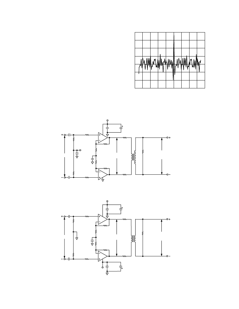
Figure 5. DMT Signal in the Time Domain
Generating DMT Signals
At this time, DMT-modulated waveforms are not typically
menu-selectable items contained within arbitrary waveform
generators. Even using (AWG) software to generate DMT sig-
nals, AWGs that are available today may not deliver DMT
signals sufficient in performance with regard to MTPR due to
limitations in the D/A converters and output drivers used by
AWG manufacturers. Similar to evaluating single-tone distor-
tion performance of an amplifier, MTPR evaluation requires a
DMT signal generator capable of delivering MTPR performance
better than that of the driver under evaluation. Generating
DMT signals can be accomplished using a Tektronics AWG
2021 equipped with Option 4, (12-/24-bit, TTL Digital Data
Out), digitally coupled to Analog Devices
’
AD9754, a 14-bit
TxDAC
, buffered by an AD8002 amplifier configured as a
differential driver. Note that the DMT waveforms, available on
the Analog Devices website, www.analog.com, or similar. WFM
files are needed to produce the necessary digital data required to
drive the TxDAC from the optional TTL Digital Data output of
the TEK AWG2021.
TxDAC is a registered trademark of Analog Devices, Inc.
相關PDF資料 |
PDF描述 |
|---|---|
| AD8019 | DSL Line Driver with Power-Down |
| AD8019AR | DSL Line Driver with Power-Down |
| AD8019ARU | DSL Line Driver with Power-Down |
| AD8019AR-EVAL | DSL Line Driver with Power-Down |
| AD8019AR-REEL | DSL Line Driver with Power-Down |
相關代理商/技術參數 |
參數描述 |
|---|---|
| AD8019ARUZ | 制造商:Analog Devices 功能描述:ADSL Driver Dual 180MHz 14-Pin TSSOP |
| AD8019ARZ | 制造商:Analog Devices 功能描述:ADSL Driver Dual 180MHz 8-Pin SOIC N |
| AD802 | 制造商:未知廠家 制造商全稱:未知廠家 功能描述:AD800/AD802: Clock Recovery and Data Retiming Phase-Locked Loop Data Sheet (Rev. B. 12/93) |
| AD80201Z | 制造商:Analog Devices 功能描述: |
發布緊急采購,3分鐘左右您將得到回復。