- 您現(xiàn)在的位置:買賣IC網(wǎng) > PDF目錄373939 > AD8176-EVAL (Analog Devices, Inc.) 475 MHz, Triple 16 】 9 Video Crosspoint Switch PDF資料下載
參數(shù)資料
| 型號(hào): | AD8176-EVAL |
| 廠商: | Analog Devices, Inc. |
| 英文描述: | 475 MHz, Triple 16 】 9 Video Crosspoint Switch |
| 中文描述: | 475兆赫,三16】9視頻交叉點(diǎn)開(kāi)關(guān) |
| 文件頁(yè)數(shù): | 22/32頁(yè) |
| 文件大小: | 489K |
| 代理商: | AD8176-EVAL |
第1頁(yè)第2頁(yè)第3頁(yè)第4頁(yè)第5頁(yè)第6頁(yè)第7頁(yè)第8頁(yè)第9頁(yè)第10頁(yè)第11頁(yè)第12頁(yè)第13頁(yè)第14頁(yè)第15頁(yè)第16頁(yè)第17頁(yè)第18頁(yè)第19頁(yè)第20頁(yè)第21頁(yè)當(dāng)前第22頁(yè)第23頁(yè)第24頁(yè)第25頁(yè)第26頁(yè)第27頁(yè)第28頁(yè)第29頁(yè)第30頁(yè)第31頁(yè)第32頁(yè)
AD8176
Preliminary Technical Data
APPLICATIONS
OPERATING MODES
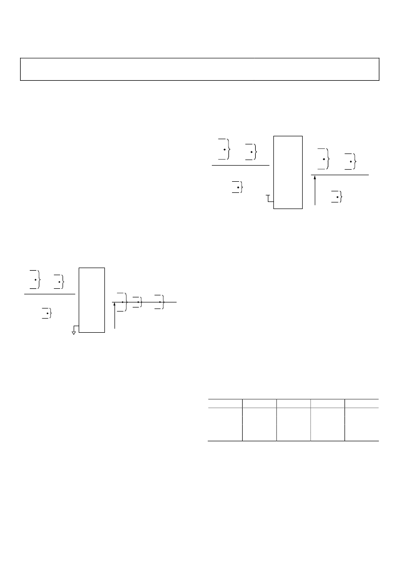
Depending on the state of the CMENC logic input, the AD8176
can be set in either of two differential-in, differential-out operat-
ing modes. Also, monitors can be driven directly by tapping the
outputs single-ended and making use of the decoded H and V
sync outputs.
Middle-of-CAT5-Run Application,
CM Encoding Turned Off
In this application, the AD8176 is placed somewhere in the
middle of a CAT5 run. By tying CMENC low, the CM of each
RGB differential pair is removed through the device (or turned
off), while the overall CM at the output is defined by the reference
value VOCM_CMENCOFF. In this mode of operation CM
noise is removed, while the intended differential RGB signals
are buffered and passed to the outputs. The AD8176 is placed in
this operation mode when used in a sync-on color scheme.
Figure 21 shows the voltage levels and CM handling for a single
input channel connected to a single output channel in a middle-
of-CAT5-run application with CM encoding turned off.
Rev. PrA | Page 22 of 32
CM
R
CM
B
DIFF. R
DIFF. B
INPUT
CM
G
DIFF. G
CMENC
AD8176
CM
R
CM
B
DIFF. R
DIFF. B
OUTPUT
CM
CM
G
DIFF. G
VOCM_CMENCOFF
0
Figure 21. AD8176 in a Middle-of-CAT5-Run Application, CM Encoding Off
(Note that in this application, the H and V outputs,
though asserted, are not used)
Inputs VBLK and VOCM_CMENCOFF allow the user
complete flexibility in defining the output CM level and the
amount of overlap between the positive and negative phases,
thus maximizing output headroom usage. Whenever VBLK
differs from VOCM_CMENCOFF by more than ±100 mV, a
differential voltage Δ
diff
is added at the outputs according to the
expression Δ
diff
= 2
×
(VBLK VOCM_CMENCOFF.)
Conversely, whenever the difference between VBLK and
VOCM_CMENCOFF is less than ±100 mV, no differential
voltage is added at the outputs.
Middle-of-CAT5-Run Application,
CM Encoding Turned On
In this application, the AD8176 is also placed somewhere in the
middle of a CAT5 run, although the common-mode handling is
different. By tying CMENC high, the CM of each RGB input is
passed through the part with a gain of +1, while at the same
time, the overall output CM is stripped and set equal to the
voltage applied at the VOCM_CMENCON pin. The AD8176 is
placed in this operation mode when used with a sync-on CM
scheme. Although asserted, the H and V outputs are not used in
this application. Figure 22 shows the voltage levels and CM
handling for a single input channel connected to a single output
channel in a middle-of-CAT5-run application with CM
encoding turned on.
CM
R
CM
B
DIFF. R
DIFF. B
INPUT
CM
G
DIFF. G
CMENC
AD8176
CM
R
CM
B
DIFF. R
DIFF. B
OUTPUT
CM
G
DIFF. G
VOCM_CMENCON
0
Figure 22. AD8176 in Middle-of-CAT5-Run Application, CM Encoding On
(Note that in this application, the H and V outputs,
though asserted, are not used)
In this operation mode, the difference Δ
diff
= 2
×
(VBLK
VOCM_CMENCOFF) still adds an output differential voltage,
as described in the previous section.
End-of-CAT5-Run, CM Encoding Turned Off—
Driving a Monitor Directly
In this application, the AD8176 is placed at the end of a CAT-5
run to drive a monitor directly
—
the differential outputs are
tapped single-ended to drive the monitor’s inputs, CMENC is
tied to logic low to remove sync-on-CM information at the
output of the part, and the decoded H and V sync outputs are
tied to the monitor’s sync inputs.
The differential-in, differential-out gain of +4 provides a
differential-in, single-ended out gain of +2 at the output pins of
the AD8176. This yields the correct differential-in, single-ended
out gain of +1 at the input of the monitor.
The relationship between the incoming sync-on CM signaling
and the H and V syncs is defined according to Table 16.
Table 16. H and V Sync Truth Table (V
POS
/V
NEG
= ±2.5 V)
CM
R
CM
G
CM
B
0.5
0
0
0
0.5
0.5
0.5
0.5
0
0
0.5
0.5
H
Low
Low
High
High
V
High
Low
Low
High
The following two statements are equivalent to the truth table
(Table 16) in producing H and V for all allowable CM inputs:
1.
H sync is high when the CM of Blue is larger than the CM
of Red
2.
V sync is high when the combined CM of Red and Blue is
larger then the CM of Green.
Hysteresis is built in, so that H and V syncs are not asserted
until the CM differences between Red, Green, and Blue differ by
more than TBD mV from each other.
相關(guān)PDF資料 |
PDF描述 |
|---|---|
| AD8176 | 475 MHz, Triple 16 】 9 Video Crosspoint Switch |
| AD8176ABPZ | 475 MHz, Triple 16 】 9 Video Crosspoint Switch |
| AD8178 | 450 MHz, Triple 16 】 5 Video Crosspoint Switch |
| AD8178ABPZ1 | 450 MHz, Triple 16 】 5 Video Crosspoint Switch |
| AD8178-EVALZ1 | 450 MHz, Triple 16 】 5 Video Crosspoint Switch |
相關(guān)代理商/技術(shù)參數(shù) |
參數(shù)描述 |
|---|---|
| AD8177 | 制造商:AD 制造商全稱:Analog Devices 功能描述:500 MHz, Triple 16 】 5 Video Crosspoint Switch |
| AD8177ABPZ | 功能描述:IC VIDEO CROSSPOINT SWIT 676BGA RoHS:是 類別:集成電路 (IC) >> 接口 - 模擬開(kāi)關(guān),多路復(fù)用器,多路分解器 系列:- 其它有關(guān)文件:STG4159 View All Specifications 標(biāo)準(zhǔn)包裝:5,000 系列:- 功能:開(kāi)關(guān) 電路:1 x SPDT 導(dǎo)通狀態(tài)電阻:300 毫歐 電壓電源:雙電源 電壓 - 電源,單路/雙路(±):±1.65 V ~ 4.8 V 電流 - 電源:50nA 工作溫度:-40°C ~ 85°C 安裝類型:表面貼裝 封裝/外殼:7-WFBGA,F(xiàn)CBGA 供應(yīng)商設(shè)備封裝:7-覆晶 包裝:帶卷 (TR) |
| AD8177-EVALZ | 制造商:AD 制造商全稱:Analog Devices 功能描述:500 MHz, Triple 16 】 5 Video Crosspoint Switch |
| AD8178 | 制造商:AD 制造商全稱:Analog Devices 功能描述:450 MHz, Triple 16 】 5 Video Crosspoint Switch |
| AD8178ABPZ | 功能描述:IC VIDEO CROSSPOINT SWIT 676BGA RoHS:是 類別:集成電路 (IC) >> 接口 - 模擬開(kāi)關(guān),多路復(fù)用器,多路分解器 系列:- 其它有關(guān)文件:STG4159 View All Specifications 標(biāo)準(zhǔn)包裝:5,000 系列:- 功能:開(kāi)關(guān) 電路:1 x SPDT 導(dǎo)通狀態(tài)電阻:300 毫歐 電壓電源:雙電源 電壓 - 電源,單路/雙路(±):±1.65 V ~ 4.8 V 電流 - 電源:50nA 工作溫度:-40°C ~ 85°C 安裝類型:表面貼裝 封裝/外殼:7-WFBGA,F(xiàn)CBGA 供應(yīng)商設(shè)備封裝:7-覆晶 包裝:帶卷 (TR) |
發(fā)布緊急采購(gòu),3分鐘左右您將得到回復(fù)。