- 您現在的位置:買賣IC網 > PDF目錄373942 > AD8306AR (ANALOG DEVICES INC) 5 MHz-400 MHz 100 dB High Precision Limiting-Logarithmic Amplifier PDF資料下載
參數資料
| 型號: | AD8306AR |
| 廠商: | ANALOG DEVICES INC |
| 元件分類: | 運動控制電子 |
| 英文描述: | 5 MHz-400 MHz 100 dB High Precision Limiting-Logarithmic Amplifier |
| 中文描述: | LOG OR ANTILOG AMPLIFIER, 395 MHz BAND WIDTH, PDSO16 |
| 封裝: | SO-16 |
| 文件頁數: | 12/16頁 |
| 文件大小: | 397K |
| 代理商: | AD8306AR |
REV. A
AD8306
–12–
Table I.
Match to 50
V
(Gain = 13 dB)
C
M
pF
Match to 100
V
(Gain = 10 dB)
C
M
pF
f
C
MHz
L
M
nH
L
M
nH
10
10.7
15
20
21.4
25
30
35
40
45
50
60
80
100
120
150
200
250
300
350
400
450
500
140
133
95.0
71.0
66.5
57.0
47.5
40.7
35.6
31.6
28.5
23.7
17.8
14.2
11.9
9.5
7.1
5.7
4.75
4.07
3.57
3.16
2.85
3500
3200
2250
1660
1550
1310
1070
904
779
682
604
489
346
262
208
155
104
75.3
57.4
45.3
36.7
30.4
25.6
100.7
94.1
67.1
50.3
47.0
40.3
33.5
28.8
25.2
22.4
20.1
16.8
12.6
10.1
8.4
6.7
5.03
4.03
3.36
2.87
2.52
2.24
2.01
4790
4460
3120
2290
2120
1790
1460
1220
1047
912
804
644
448
335
261
191
125
89.1
66.8
52.1
41.8
34.3
28.6
General Matching Procedure
For other center frequencies and source impedances, the following
method can be used to calculate the basic matching parameters.
Step 1: Tune Out C
IN
At a center frequency f
C
, the shunt impedance of the input
capacitance C
IN
can be made to disappear by resonating with a
temporary inductor L
IN
, whose value is given by
L
IN
=
1/{(2
π
f
C
)
2
C
IN
}
=
10
10
/f
C
2
when
C
IN
= 2.5 pF. For example, at
f
C
= 100 MHz,
L
IN
= 1
μ
H.
(7)
Step 2: Calculate C
O
and L
O
Now having a purely resistive input impedance, we can calculate
the nominal coupling elements C
O
and L
O
, using
C
f
R R
L
R R
π
f
O
C
M
O
M
C
=
(
)
=
(
)
1
2
2
π
;
(8)
For the AD8306, R
IN
is 1 k
. Thus, if a match to 50
is
needed, at f
C
= 100 MHz, C
O
must be 7.12 pF and L
O
must be
356 nH.
Step 3: Split C
O
Into Two Parts
Since we wish to provide the fully-balanced form of network
shown in Figure 28, two capacitors C1 = C2
each of nominally
twice C
O
, shown as C
M
in the figure, can be used. This requires
a value of 14.24 pF in this example. Under these conditions, the
voltage amplitudes at INHI and INLO will be similar. A some-
what better balance in the two drives may be achieved when C1
is made slightly larger than C2, which also allows a wider range
of choices in selecting from standard values. For example, ca-
pacitors of C1 = 15 pF and C2 = 13 pF may be used (making
C
O
= 6.96 pF).
Step 4: Calculate L
M
The matching inductor required to provide both L
IN
and L
O
is
just the parallel combination of these:
L
M
= L
IN
L
O
/(
L
IN
+
L
O
)
With
L
IN
= 1
μ
H and
L
O
= 356 nH, the value of
L
M
to complete
this example of a match of 50
at 100 MHz is 262.5 nH. The
nearest standard value of 270 nH may be used with only a slight
loss of matching accuracy. The voltage gain at resonance de-
pends only on the ratio of impedances, as is given by
(9)
GAIN
R
R
R
R
IN
S
IN
S
=
=
20
10
log
log
(10)
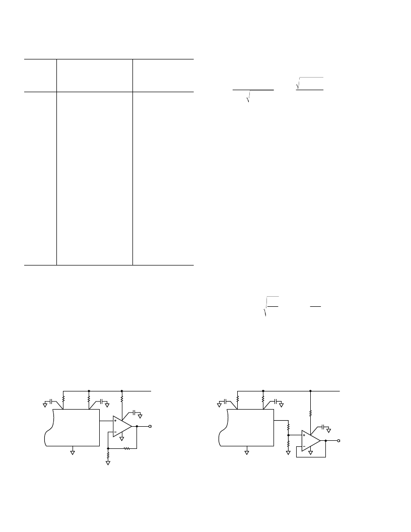
Altering the Logarithmic Slope
Simple schemes can be used to increase and decrease the loga-
rithmic slope as shown in Figure 30. For the AD8306, only
power, ground and logarithmic output connections are shown;
refer to Figure 24 for complete circuitry. In Figure 30(a), the op
amp’s gain of +2 increases the slope to 40 mV/dB. In Figure
30(b), the AD8031 buffers a resistive divider to give a slope of
Figure 30. Altering the Logarithmic Slope
VPS1
VPS2
PADL, COM1, COM2
AD8306
10
V
10
V
0.1
m
F
0.1
m
F
5k
V
5k
V
AD8031
0.1
m
F
10
V
+5V
40mV/dB
VLOG
(a)
VPS1
VPS2
PADL, COM1, COM2
AD8306
10
V
10
V
0.1
m
F
0.1
m
F
AD8031
0.1
m
F
10
V
10mV/dB
5k
V
5k
V
+5V
VLOG
(b)
相關PDF資料 |
PDF描述 |
|---|---|
| AD8306AR-REEL | 5 MHz-400 MHz 100 dB High Precision Limiting-Logarithmic Amplifier |
| AD8306AR-REEL7 | 5 MHz-400 MHz 100 dB High Precision Limiting-Logarithmic Amplifier |
| AD8307AN | Low Cost DC-500 MHz, 92 dB Logarithmic Amplifier |
| AD8307AR | Low Cost DC-500 MHz, 92 dB Logarithmic Amplifier |
| AD8307AR-REEL7 | Low Cost DC-500 MHz, 92 dB Logarithmic Amplifier |
相關代理商/技術參數 |
參數描述 |
|---|---|
| AD8306AR-REEL | 制造商:Analog Devices 功能描述:SP Amp LOG Amp Single 6.5V 16-Pin SOIC N T/R |
| AD8306AR-REEL7 | 功能描述:IC LOG-LIMITING AMP HP 16-SOIC RoHS:否 類別:集成電路 (IC) >> 線性 - 放大器 - 專用 系列:- 產品培訓模塊:Lead (SnPb) Finish for COTS Obsolescence Mitigation Program 標準包裝:60 系列:- 類型:可變增益放大器 應用:CATV 安裝類型:表面貼裝 封裝/外殼:20-WQFN 裸露焊盤 供應商設備封裝:20-TQFN-EP(5x5) 包裝:托盤 |
| AD8306ARZ | 功能描述:IC LOG-LIMITING AMP 16-SOIC RoHS:是 類別:集成電路 (IC) >> 線性 - 放大器 - 專用 系列:- 產品培訓模塊:Lead (SnPb) Finish for COTS Obsolescence Mitigation Program 標準包裝:60 系列:- 類型:可變增益放大器 應用:CATV 安裝類型:表面貼裝 封裝/外殼:20-WQFN 裸露焊盤 供應商設備封裝:20-TQFN-EP(5x5) 包裝:托盤 |
| AD8306ARZ | 制造商:Analog Devices 功能描述:Logarithmic Amplifier IC |
| AD8306ARZ-REEL | 制造商:Analog Devices 功能描述:SP Amp LOG Amp Single 6.5V 16-Pin SOIC N T/R 制造商:Analog Devices 功能描述:SP AMP LOG AMP SGL 6.5V 16SOIC N - Tape and Reel |
發布緊急采購,3分鐘左右您將得到回復。