- 您現在的位置:買賣IC網 > PDF目錄373942 > AD8307 (Analog Devices, Inc.) Low Cost DC-500 MHz, 92 dB Logarithmic Amplifier(對數放大器) PDF資料下載
參數資料
| 型號: | AD8307 |
| 廠商: | Analog Devices, Inc. |
| 元件分類: | 運動控制電子 |
| 英文描述: | Low Cost DC-500 MHz, 92 dB Logarithmic Amplifier(對數放大器) |
| 中文描述: | 低成本DC - 500兆赫,九十二分貝對數放大器(對數放大器) |
| 文件頁數: | 7/20頁 |
| 文件大小: | 303K |
| 代理商: | AD8307 |
AD8307
–7–
REV. 0
LOG AMP T HE ORY
Logarithmic amplifiers perform a more complex operation than
that of classical linear amplifiers, and their circuitry is signifi-
cantly different. A good grasp of what log amps do, and how
they do it, will avoid many pitfalls in their application. T he
essential purpose of a log amp is not to amplify, though amplifi-
cation is utilized to achieve the function. Rather, it is to com-
press a signal of wide dynamic range to its decibel equivalent. It
is thus a
measurement device. A better term might be logarith-
mic converter, since its basic function is the conversion of a
signal from one domain of representation to another, via a precise
nonlinear transformation.
Logarithmic compression leads to situations that may be con-
fusing or paradoxical. For example, a voltage offset added to
the output of a log amp is equivalent to a gain increase ahead of
its input. In the usual case where all the variables are voltages,
and regardless of the particular structure, the relationship between
the variables can be expressed as:
V
OUT
=
V
Y
log
(
V
IN
/
V
X
)
where:
V
OUT
is the output voltage,
V
Y
is called the slope voltage; the logarithm is usually taken
to base-ten (in which case
V
Y
is also the volts-per-decade),
V
IN
is the input voltage,
and
V
X
is called the intercept voltage.
All log amps implicitly require two references, here V
X
and V
Y
,
which determine the scaling of the circuit. T he absolute accu-
racy of a log amp cannot be any better than the accuracy of its
scaling references. Equation 1 is mathematically incomplete in
representing the behavior of a demodulating log amp such as
the AD8307, where V
IN
has an alternating sign. However, the
basic principles are unaffected, and we can safely use this as our
starting point in the analyses of log amp scaling which follow.
(1)
V
OUT
5V
Y
4V
Y
3V
Y
2V
Y
V
Y
–2V
Y
V
OUT
= 0
LOG V
IN
V
SHIFT
LOWER INTERCEPT
V
IN
= 10
–2
V
X
–40dBc
V
IN
= 10
2
V
X
+40dBc
V
IN
= 10
4
V
X
+80dBc
V
= V
X
0dBc
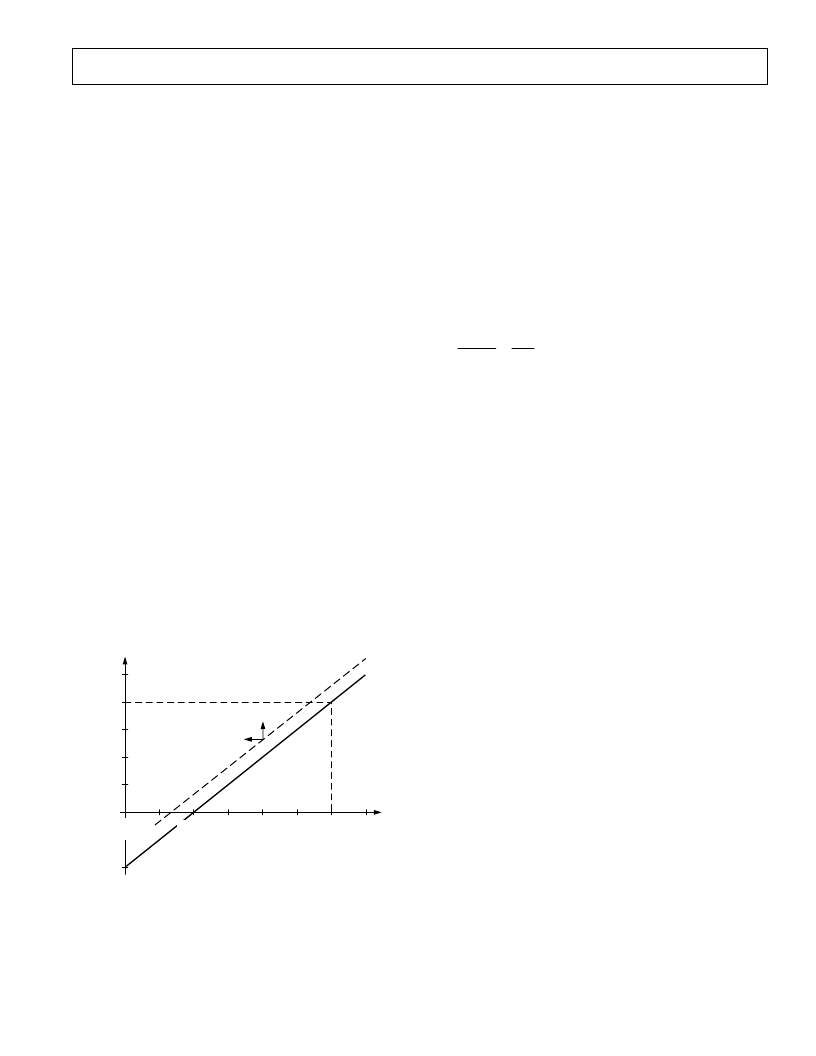
Figure 19. Ideal Log Amp Function
Figure 19 shows the input/output relationship of an ideal log
amp, conforming to Equation 1. T he horizontal scale is loga-
rithmic and spans a wide dynamic range, shown here as over
120 dB, or six decades. T he output passes through zero (the
log-intercept) at the unique value V
IN
= V
X
and would ideally
become negative for inputs below the intercept. In the ideal
case, the straight line describing V
OUT
for all values of V
IN
would
continue indefinitely in both directions. T he dotted line shows
that the effect of adding an offset voltage V
SHIFT
to the output is
to lower the effective intercept voltage V
X
. Exactly the same
alteration could be achieved raising the gain (or signal level)
ahead of the log amp by the factor V
SHIFT
/V
Y
. For example, if
V
Y
is 500 mV per decade (that is, 25 mV/dB, as for the AD8307),
an offset of +150 mV added to the output will appear to lower
the intercept by two tenths of a decade, or 6 dB. Adding an
offset to the output is thus indistinguishable from applying an
input level that is 6 dB higher.
T he log amp function described by Equation 1 differs from that
of a linear amplifier in that the incremental gain
V
OUT
/
V
IN
is a
very strong function of the instantaneous value of V
IN
, as is
apparent by calculating the derivative. For the case where the
logarithmic base is
e
, we have:
V
OUT
V
IN
=
V
Y
V
IN
(2)
T hat is, the incremental gain is inversely proportional to the
instantaneous value of the input voltage. T his remains true for
any logarithmic base, which is chosen as 10 for all decibel-
related purposes. It follows that a perfect log amp would be
required to have infinite gain under classical small-signal (zero-
amplitude) conditions. Less ideally, this result indicates that,
whatever means are used to implement a log amp, accurate
response under small-signal conditions (that is, at the lower end
of the dynamic range) demands the provision of a very high
gain-bandwidth product. A further consequence of this high
gain is that, in the absence of an input signal, even very small
amounts of thermal noise at the input of a log amp will cause a
finite output for zero input, resulting in the response line curving
away from the ideal shown in Figure 19 toward a finite baseline,
which can be either above or below the intercept. Note that the
value given for this intercept may be an extrapolated value, in
which case the output may not cross zero, or even reach it, as is
the case for the AD8307.
While Equation 1 is fundamentally correct, a simpler formula is
appropriate for specifying the calibration attributes of a log amp
like the AD8307, which demodulates a sine wave input:
V
OUT
=
V
SLOPE
(
P
IN
–
P
0
)
where:
V
OUT
is the demodulated and filtered baseband (video or
RSSI) output,
V
SLOPE
is the logarithmic slope, now expressed in volts/dB
(typically between 15 and 30 mV/dB),
P
IN
is the input power, expressed in decibels relative to some
reference power level,
and
P
0
is the logarithmic intercept, expressed in decibels relative
to the same reference level.
T he most widely used reference in RF systems is decibels above
1 mW in 50
, written dBm. Note that the quantity (P
IN
– P
0
) is
just dB. T he logarithmic function disappears from the formula
because the conversion has already been implicitly performed in
stating the input in decibels. T his is strictly a concession to popu-
lar convention: log amps manifestly do not respond to power
(tacitly, power absorbed at the input), but, rather, to input
(3)
相關PDF資料 |
PDF描述 |
|---|---|
| AD8309ARU-REEL | 5 MHz.500 MHz 100 dB Demodulating Logarithmic Amplifier with Limiter Output |
| AD8309-EVAL | 5 MHz.500 MHz 100 dB Demodulating Logarithmic Amplifier with Limiter Output |
| AD8309ARU | 5 MHz.500 MHz 100 dB Demodulating Logarithmic Amplifier with Limiter Output |
| AD8309ARU-REEL7 | 5 MHz.500 MHz 100 dB Demodulating Logarithmic Amplifier with Limiter Output |
| AD830 | High Speed, Video Difference Amplifier(高速,視頻差分運放) |
相關代理商/技術參數 |
參數描述 |
|---|---|
| AD8307_06 | 制造商:AD 制造商全稱:Analog Devices 功能描述:Low Cost DC-500 MHz, 92 dB Logarithmic Amplifier |
| AD8307AN | 功能描述:IC LOGARITHMIC AMP 8-DIP RoHS:否 類別:集成電路 (IC) >> 線性 - 放大器 - 專用 系列:- 產品培訓模塊:Lead (SnPb) Finish for COTS Obsolescence Mitigation Program 標準包裝:60 系列:- 類型:可變增益放大器 應用:CATV 安裝類型:表面貼裝 封裝/外殼:20-WQFN 裸露焊盤 供應商設備封裝:20-TQFN-EP(5x5) 包裝:托盤 |
| AD8307ANZ | 功能描述:IC LOGARITHMIC AMP 8-DIP RoHS:是 類別:集成電路 (IC) >> 線性 - 放大器 - 專用 系列:- 產品培訓模塊:Lead (SnPb) Finish for COTS Obsolescence Mitigation Program 標準包裝:60 系列:- 類型:可變增益放大器 應用:CATV 安裝類型:表面貼裝 封裝/外殼:20-WQFN 裸露焊盤 供應商設備封裝:20-TQFN-EP(5x5) 包裝:托盤 |
| AD8307AR | 功能描述:IC LOGARITHMIC AMP 92DB 8-SOIC RoHS:否 類別:集成電路 (IC) >> 線性 - 放大器 - 專用 系列:- 產品培訓模塊:Lead (SnPb) Finish for COTS Obsolescence Mitigation Program 標準包裝:60 系列:- 類型:可變增益放大器 應用:CATV 安裝類型:表面貼裝 封裝/外殼:20-WQFN 裸露焊盤 供應商設備封裝:20-TQFN-EP(5x5) 包裝:托盤 |
| AD8307AR-REEL | 功能描述:IC LOGARITHMIC AMP 8-SOIC T/R RoHS:否 類別:集成電路 (IC) >> 線性 - 放大器 - 專用 系列:- 產品培訓模塊:Lead (SnPb) Finish for COTS Obsolescence Mitigation Program 標準包裝:60 系列:- 類型:可變增益放大器 應用:CATV 安裝類型:表面貼裝 封裝/外殼:20-WQFN 裸露焊盤 供應商設備封裝:20-TQFN-EP(5x5) 包裝:托盤 |
發布緊急采購,3分鐘左右您將得到回復。