- 您現在的位置:買賣IC網 > PDF目錄373969 > AD9870EB (Analog Devices, Inc.) IF Digitizing Subsystem PDF資料下載
參數資料
| 型號: | AD9870EB |
| 廠商: | Analog Devices, Inc. |
| 英文描述: | IF Digitizing Subsystem |
| 中文描述: | 中頻數字化子系統 |
| 文件頁數: | 8/20頁 |
| 文件大小: | 233K |
| 代理商: | AD9870EB |
REV. 0
AD9870
–8–
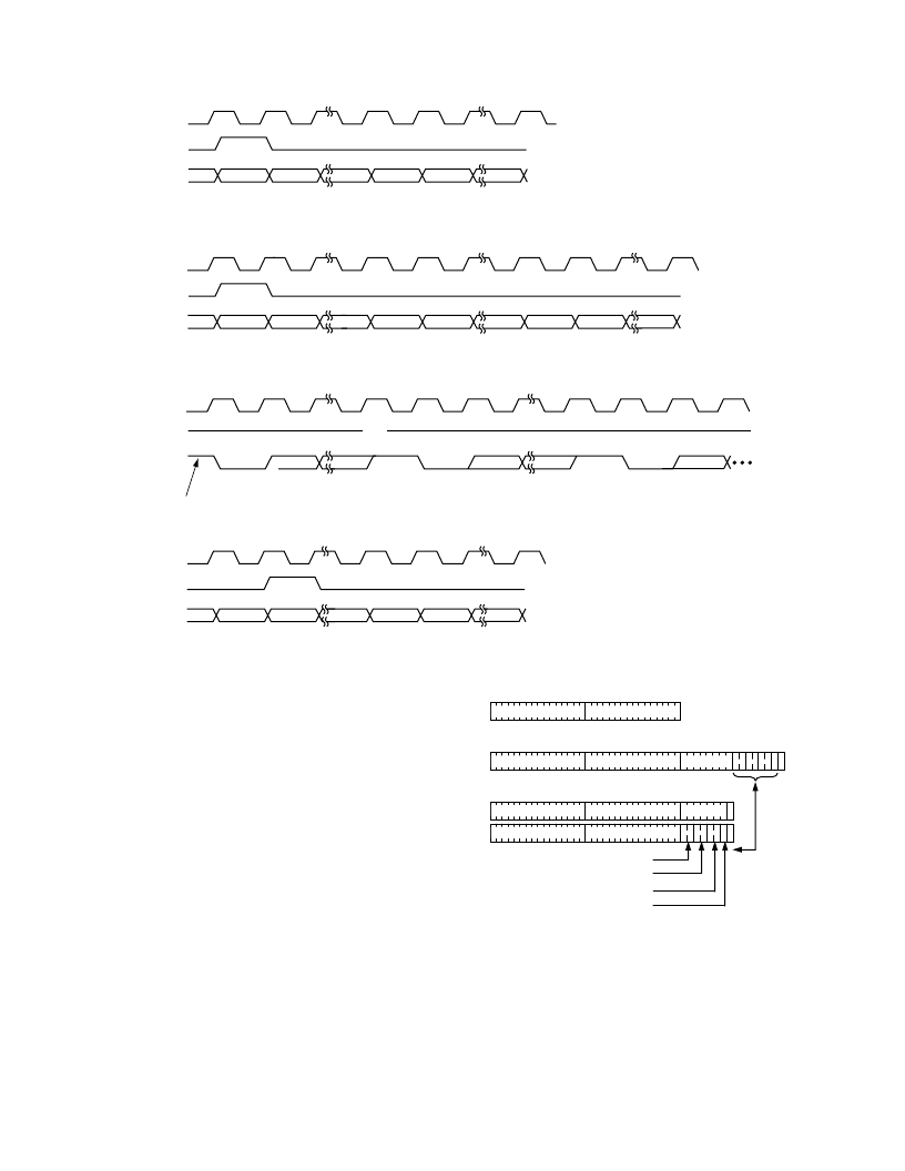
The two optional bytes are output if the EAGC bit of SSICRA
is set. The first byte contains the eight most significant bits of
the AGC DAC setting while the second byte contains a 2-bit
overload field, a 2-bit reset field, a 2-bit large-signal field, a zero
bit, and a trailing high bit. The overload, reset, and large-signal
fields contain the number of overload, reset, and large-signal
events since the last report, respectively, saturating at three
should the number of events equal or exceed this amount. The
two optional bytes follow the I and Q data as a 16-bit word
provided the AAGC bit of SSICRA is not set. If the AAGC bit
is set, the two bytes follow the I and Q data in an alternating
fashion. In this “alternate AGC data” mode, the LSB of the
byte containing the AGC DAC setting is zero; the LSB of the
byte containing reset/overload information is always a one.
Figure 3 illustrates the fields of the SSI data frames.
EAGC = 0, AAGC = X: 32 DATA BITS
EAGC = 1, AAGC = 0: 48 DATA BITS
EAGC = 1, AAGC = 1: 40 DATA BITS
I (15:0)
Q (15:0)
I (15:0)
Q (15:0)
AGC (7:0)
1
I (15:0)
Q (15:0)
AGC (7:1) 0
I (15:0)
Q (15:0)
1
OVERLOAD COUNT
RESET COUNT
DON
’
T CARE
FGM
SAME
Figure 3. SSI Frame Structure
FS
DOUT
CLKOUT
FS
DOUT
CLKOUT
FS
DOUT
SCKI = 0, SCKT = 0, SLFS = X, SFSI = X, EFS = 1, SFST = 1, EAGC = 0
SCKI = 0, SCKT = 0, SLFS = X, SFSI = X, EFS = 1, SFST = 1, EAGC = 0: AS ABOVE, BUT FS IS LOW
IDLE (HIGH) BITS
CLKOUT
SCKI = 0, SCKT = 0, SLFS = 0, SFSI = 0, EFS = 0, SFST = 0, EAGC = 1, AAGC = 0
I15
I0
Q15
Q14
Q0
G15
G14
G0
CLKOUT
FS
DOUT
SCKI = 0, SCKT = 0, SLFS = 1, SFSI = 0, EFS = 0, SFST = 0, EAGC = 0
I15
I0
Q15
Q14
Q0
START
BIT
START
BIT
STOP
BIT
STOP
BIT
START
BIT
HI-Z
SCKI = 0, SCKT = 0, SLFS = 0, SFSI = 0, EFS = 0, SFST = 0, EAGC = 0
I15
I8
I7
I0
Q15
I15
I0
Q15
Q14
Q0
Figure 2. SSI Timing for Several SSICR Settings
相關PDF資料 |
PDF描述 |
|---|---|
| AD9873 | Analog Front End Converter for Set-Top Box, Cable Modem |
| AD9873-EB | Analog Front End Converter for Set-Top Box, Cable Modem |
| AD9873JS | Analog Front End Converter for Set-Top Box, Cable Modem |
| AD9874 | IF Digitizing Subsystem |
| AD9874BST | IF Digitizing Subsystem |
相關代理商/技術參數 |
參數描述 |
|---|---|
| AD9873 | 制造商:AD 制造商全稱:Analog Devices 功能描述:Analog Front End Converter for Set-Top Box, Cable Modem |
| AD9873-EB | 制造商:Analog Devices 功能描述: |
| AD9873JS | 制造商:Analog Devices 功能描述: |
| AD9874 | 制造商:AD 制造商全稱:Analog Devices 功能描述:IF Digitizing Subsystem |
| AD9874ABST | 功能描述:IC IF DIGIT SUBSYSTEM 48-LQFP RoHS:否 類別:RF/IF 和 RFID >> RF 其它 IC 和模塊 系列:- 標準包裝:100 系列:* |
發布緊急采購,3分鐘左右您將得到回復。