- 您現在的位置:買賣IC網 > PDF目錄373995 > ADM1021 (Analog Devices, Inc.) Low Cost Microprocessor System Temperature Monitor PDF資料下載
參數資料
| 型號: | ADM1021 |
| 廠商: | Analog Devices, Inc. |
| 英文描述: | Low Cost Microprocessor System Temperature Monitor |
| 中文描述: | 低成本的微處理器系統溫度監控 |
| 文件頁數: | 10/12頁 |
| 文件大小: | 139K |
| 代理商: | ADM1021 |
ADM1021
–10–
REV. 0
ALERT
OUTPUT
The
ALERT
output goes low whenever an out-of limit measure-
ment is detected, or if the remote temperature sensor is open-
circuit. It is an open-drain and requires a 10 k
pull-up to V
DD
.
Several
ALERT
outputs can be wire-ANDED together, so that
the common line will go low if one or more of the
ALERT
out-
puts goes low.
The
ALERT
output can be used as an interrupt signal to a
processor, or it may be used as an
SMBALERT
. Slave devices
on the SMBus can normally not signal to the master that they
want to talk, but the
SMBALERT
function allows them to do
so.
One or more
ALERT
outputs are connected to a common
SMBALERT
line connected to the master. When the
SMBALERT
line is pulled low by one of the devices, the following procedure
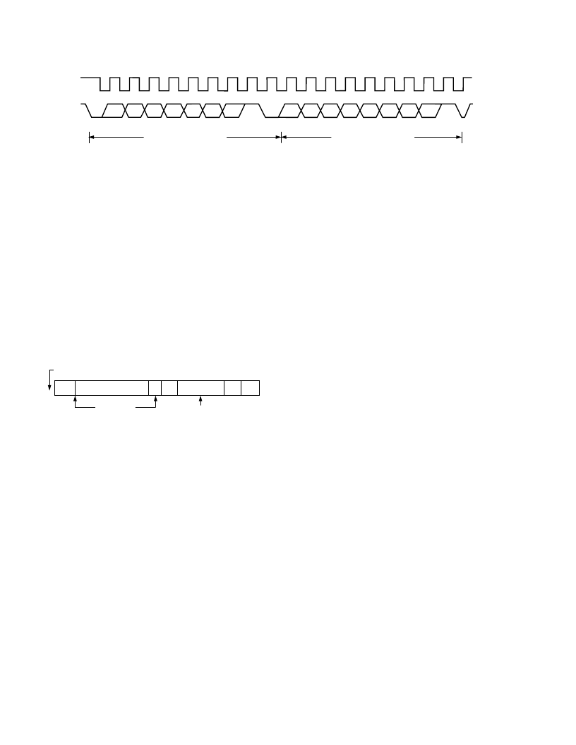
occurs as illustrated in Figure 16.
MASTER
ARA AND READ
COMMAND
DEVICE SENDS
ITS ADDRESS
NO
ACK
START
ALERT RESPONSE ADDRESS
RD
ACK
DEVICE ADDRESS
STOP
Figure 16. Use of
SMBALERT
1.
SMBALERT
pulled low.
2. Master initiates a read operation and sends the Alert Re-
sponse Address (ARA = 0001 100). This is a general call
address that must not be used as a specific device address.
3. The device whose
ALERT
output is low responds to the
Alert Response Address and the master reads its device ad-
dress. The address of the device is now known and it can be
interrogated in the usual way.
4. If more than one device’s
ALERT
output is low, the one with
the lowest device address, will have priority, in accordance
with normal SMBus arbitration.
5. Once the ADM1021 has responded to the Alert Response
Address, it will reset its
ALERT
output, provided that the
error condition that caused the
ALERT
no longer exists. If
the
SMBALERT
line remains low, the master will send
ARA again, and so on until all devices whose
ALERT
out-
puts were low have responded.
LOW POWER STANDBY MODES
The ADM1021 can be put into a low power standby mode
using hardware or software, that is by taking the
STBY
input
low, or by setting Bit 6 of the Configuration Register. When
STBY
is high, or Bit 6 is low, the ADM1021 operates normally.
When
STBY
is pulled low or Bit 6 is high, the ADC is inhibited,
any conversion in progress is terminated without writing the
result to the corresponding value register.
The SMBus is still enabled. Power consumption in the standby
mode is reduced to less than 10
μ
A if there is no SMBus activ-
ity, or 100
μ
A if there are clock and data signals on the bus.
These two modes are similar but not identical. When
STBY
is
low, conversions are completely inhibited. When Bit 6 is set but
STBY
is high, a one-shot conversion of both channels can be
initiated by writing XXh to the One-Shot Register (address 0Fh).
SENSOR FAULT DETECTION
The ADM1021 has a fault detector at the D+ input that detects
if the external sensor diode is open-circuit. This is a simple
voltage comparator that trips if the voltage at D+ exceeds V
CC
–
1 V (typical). The output of this comparator is checked when a
conversion is initiated, and sets Bit 2 of the Status Register if a
fault is detected.
If the remote sensor voltage falls below the normal measuring
range, for example due to the diode being short-circuited, the
ADC will output –128
°
C (1000 0000). Since the normal operat-
ing temperature range of the device only extends down to –55
°
C,
this output code should never be seen in normal operation, so it
can be interpreted as a fault condition. Since it will be outside
the power-on default low temperature limit (–55
°
C) and any
low limit that would normally be programmed, a short-circuit
sensor will cause an SMBus alert.
In this respect, the ADM1021 differs from and improves upon
competitive devices that output zero if the external sensor goes
short-circuit. These devices can misinterpret a genuine 0
°
C
measurement as a fault condition.
If the external diode channel is not being used and it is shorted
out, then the resulting
ALERT
may be cleared by writing 80h
(–128
°
C) to the low limit register.
R/
W
A6
SCLK
SDATA
A5
A4
A3
A2
A1
A0
D7
D6
D5
D4
D3
D2
D1
D0
NO ACK.
BY MASTER
STOP BY
MASTER
START BY
MASTER
1
9
1
ACK. BY
ADM1021
9
FRAME 1
SERIAL BUS ADDRESS BYTE
FRAME 2
DATA BYTE FROM ADM1021
Figure 15. Reading Data from a Previously Selected Register
相關PDF資料 |
PDF描述 |
|---|---|
| ADM1021ARQ | Low Cost Microprocessor System Temperature Monitor |
| ADM1022 | Low-Cost PC Temperature Monitor and Fan Control ASIC |
| ADM1022ARQ | Low-Cost PC Temperature Monitor and Fan Control ASIC |
| ADM1023 | LJT 6C 6#12 PIN PLUG |
| ADM1023ARQ | ACPI-Compliant High-Accuracy Microprocessor System Temperature Monitor |
相關代理商/技術參數 |
參數描述 |
|---|---|
| ADM102-11/12VDC | 制造商:未知廠家 制造商全稱:未知廠家 功能描述:Analog IC |
| ADM102-11/24VDC | 制造商:未知廠家 制造商全稱:未知廠家 功能描述:Analog IC |
| ADM102-11/48VDC | 制造商:未知廠家 制造商全稱:未知廠家 功能描述:Analog IC |
| ADM1021A | 制造商:ONSEMI 制造商全稱:ON Semiconductor 功能描述:Low Cost Microprocessor System Temperature Monitor Microcomputer |
| ADM1021AARQ | 功能描述:IC SENSOR TEMP DUAL3/5.5V 16QSOP RoHS:否 類別:集成電路 (IC) >> PMIC - 熱管理 系列:- 標準包裝:1 系列:- 功能:溫度監控系統(傳感器) 傳感器類型:內部和外部 感應溫度:-40°C ~ 125°C,外部傳感器 精確度:±2.5°C 本地(最大值),±5°C 遠程(最大值) 拓撲:ADC,比較器,寄存器庫 輸出類型:2 線 SMBus? 輸出警報:無 輸出風扇:無 電源電壓:2.7 V ~ 5.5 V 工作溫度:-40°C ~ 125°C 安裝類型:表面貼裝 封裝/外殼:SOT-23-8 供應商設備封裝:SOT-23-8 包裝:Digi-Reel® 其它名稱:296-22675-6 |
發布緊急采購,3分鐘左右您將得到回復。