- 您現在的位置:買賣IC網 > PDF目錄373995 > ADM1021 (Analog Devices, Inc.) Low Cost Microprocessor System Temperature Monitor PDF資料下載
參數資料
| 型號: | ADM1021 |
| 廠商: | Analog Devices, Inc. |
| 英文描述: | Low Cost Microprocessor System Temperature Monitor |
| 中文描述: | 低成本的微處理器系統溫度監控 |
| 文件頁數: | 5/12頁 |
| 文件大小: | 139K |
| 代理商: | ADM1021 |
ADM1021
–5–
REV. 0
FREQUENCY – Hz
10
050
50M
500
T
8
C
5k
50k
500k
5M
6
5
4
2
1
3
10mV SQ. WAVE
9
8
7
100k
25M
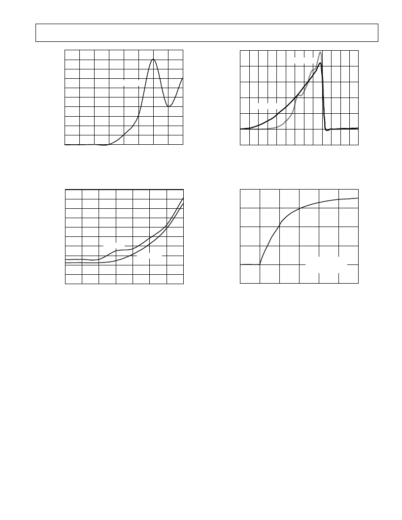
Figure 8. Temperature Error vs. Differential-Mode Noise
Frequency
CONVERSION RATE – Hz
200
0
0.0625
8
0.125
S
m
A
0.25
0.5
1
2
4
180
80
60
40
20
140
100
160
120
V
CC
= +5V
V
CC
= +3.3V
Figure 9. Operating Supply Current vs. Conversion
Rate
SUPPLY VOLTAGE – Volts
100
40
–200
1.1
S
m
A
1.3
1.5 1.7
1.9
2.1
2.3 2.5
2.7
2.9
3.5
4.5
80
60
20
0
ADDX = HI-Z
ADDX = GND
Figure 10. Standby Supply Current vs. Supply Voltage
TIME – Sec
125
100
0
T = 0
T = 10
T = 2
T
8
C
T = 4
T = 6
T = 8
75
50
25
IMMERSED
IN +115
C
FLUORINERT BATH
Figure 11. Response to Thermal Shock
FUNCTIONAL DESCRIPTION
The ADM1021 contains a two-channel A-to-D converter with
special input-signal conditioning to enable operation with remote
and on-chip diode temperature sensors. When the ADM1021 is
operating normally, the A-to-D converter operates in a free-
running mode. The analog input multiplexer alternately selects
either the on-chip temperature sensor to measure its local tem-
perature, or the remote temperature sensor. These signals are
digitized by the ADC and the results stored in the Local and
Remote Temperature Value Registers as 8-bit, twos complement
words.
The measurement results are compared with Local and Remote,
High and Low Temperature Limits, stored in four on-chip regis-
ters. Out-of-limit comparisons generate flags that are stored in
the status register, and one or more out-of-limit results will
cause the
ALERT
output to pull low.
The limit registers can be programmed, and the device con-
trolled and configured, via the serial System Management Bus.
The contents of any register can also be read back via the SMBus.
Control and configuration functions consist of:
Switching the device between normal operation and standby
mode.
Masking or enabling the
ALERT
output.
Selecting the conversion rate.
MEASUREMENT METHOD
A simple method of measuring temperature is to exploit the
negative temperature coefficient of a diode, or the base-emitter
voltage of a transistor, operated at constant current. Unfortu-
nately, this technique requires calibration to null out the effect
of the absolute value of V
be
, which varies from device to device.
The technique used in the ADM1021 is to measure the change
in V
be
when the device is operated at two different currents.
This is given by:
V
be
=
KT
/
q
×
ln
(
N
)
where:
K
is Boltzmann’s constant
q
is charge on the electron (1.6 x 10
–19
Coulombs)
T
is absolute temperature in Kelvins
N
is ratio of the two currents
相關PDF資料 |
PDF描述 |
|---|---|
| ADM1021ARQ | Low Cost Microprocessor System Temperature Monitor |
| ADM1022 | Low-Cost PC Temperature Monitor and Fan Control ASIC |
| ADM1022ARQ | Low-Cost PC Temperature Monitor and Fan Control ASIC |
| ADM1023 | LJT 6C 6#12 PIN PLUG |
| ADM1023ARQ | ACPI-Compliant High-Accuracy Microprocessor System Temperature Monitor |
相關代理商/技術參數 |
參數描述 |
|---|---|
| ADM102-11/12VDC | 制造商:未知廠家 制造商全稱:未知廠家 功能描述:Analog IC |
| ADM102-11/24VDC | 制造商:未知廠家 制造商全稱:未知廠家 功能描述:Analog IC |
| ADM102-11/48VDC | 制造商:未知廠家 制造商全稱:未知廠家 功能描述:Analog IC |
| ADM1021A | 制造商:ONSEMI 制造商全稱:ON Semiconductor 功能描述:Low Cost Microprocessor System Temperature Monitor Microcomputer |
| ADM1021AARQ | 功能描述:IC SENSOR TEMP DUAL3/5.5V 16QSOP RoHS:否 類別:集成電路 (IC) >> PMIC - 熱管理 系列:- 標準包裝:1 系列:- 功能:溫度監控系統(傳感器) 傳感器類型:內部和外部 感應溫度:-40°C ~ 125°C,外部傳感器 精確度:±2.5°C 本地(最大值),±5°C 遠程(最大值) 拓撲:ADC,比較器,寄存器庫 輸出類型:2 線 SMBus? 輸出警報:無 輸出風扇:無 電源電壓:2.7 V ~ 5.5 V 工作溫度:-40°C ~ 125°C 安裝類型:表面貼裝 封裝/外殼:SOT-23-8 供應商設備封裝:SOT-23-8 包裝:Digi-Reel® 其它名稱:296-22675-6 |
發布緊急采購,3分鐘左右您將得到回復。