- 您現在的位置:買賣IC網 > PDF目錄374016 > ADMC401-ADVEVALKIT (Analog Devices, Inc.) Circular Connector; No. of Contacts:5; Series:MS27497; Body Material:Aluminum; Connecting Termination:Crimp; Connector Shell Size:10; Circular Contact Gender:Pin; Circular Shell Style:Wall Mount Receptacle; Insert Arrangement:10-5 RoHS Compliant: No PDF資料下載
參數資料
| 型號: | ADMC401-ADVEVALKIT |
| 廠商: | Analog Devices, Inc. |
| 元件分類: | 圓形連接器 |
| 英文描述: | Circular Connector; No. of Contacts:5; Series:MS27497; Body Material:Aluminum; Connecting Termination:Crimp; Connector Shell Size:10; Circular Contact Gender:Pin; Circular Shell Style:Wall Mount Receptacle; Insert Arrangement:10-5 RoHS Compliant: No |
| 中文描述: | 單芯片,基于DSP的高性能電機控制器 |
| 文件頁數: | 38/60頁 |
| 文件大小: | 417K |
| 代理商: | ADMC401-ADVEVALKIT |
第1頁第2頁第3頁第4頁第5頁第6頁第7頁第8頁第9頁第10頁第11頁第12頁第13頁第14頁第15頁第16頁第17頁第18頁第19頁第20頁第21頁第22頁第23頁第24頁第25頁第26頁第27頁第28頁第29頁第30頁第31頁第32頁第33頁第34頁第35頁第36頁第37頁當前第38頁第39頁第40頁第41頁第42頁第43頁第44頁第45頁第46頁第47頁第48頁第49頁第50頁第51頁第52頁第53頁第54頁第55頁第56頁第57頁第58頁第59頁第60頁
REV. B
ADMC401
–38–
asynchronous timing of encoder and DSP-reading events. As a
result, more accurate computations of the position and velocity
of the motor shaft may be performed.
The EET consists of a 16-bit encoder event timer, an encoder
pulse decimator and a clock divider. The EET clock frequency is
selected by the 16-bit read/write EETDIV clock divide register,
whose value divides the CLKOUT frequency. The contents of
the encoder event timer are incremented on each rising edge of
the divided clock signal. An EETDIV value of zero gives the
maximum divide value of 0x10000 (= 65,536), so that the
clock frequency to the encoder event timer is at its minimum
possible value.
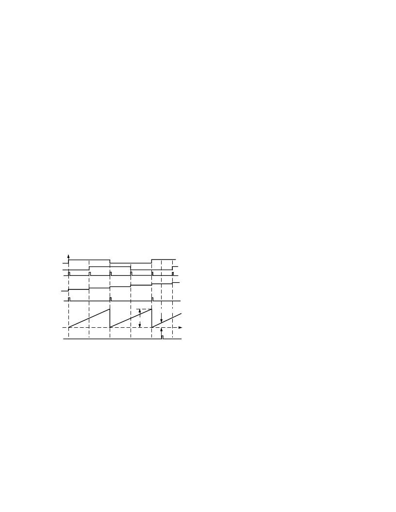
The quadrature signal from the encoder interface unit is deci-
mated at a rate determined by the 8-bit read/write EETN regis-
ter. For example, writing a value of two to EETN, produces a
pulse decimator output train at half the quadrature signal fre-
quency, as shown in Figure 31. The rising edge of this deci-
mated signal is termed a velocity event. Therefore, for an EETN
value of two, a velocity event occurs every two encoder edges, or
on each edge of one of the encoder signals. An EETN value of 0
gives an effective pulse decimation value of 256.
On the occurrence of a velocity event, the contents of the en-
coder event timer are stored in an intermediate Interval Time
Register. Under normal operation, this register stores the elapsed
time between successive velocity events. After the timer value
has been latched at the velocity event, the contents of the en-
coder event timer are reset to one.
ENCODER EVENT
TIMER VALUE
EET LATCH
EVENT
VELOCITY
EVENTS
QUADRATURE
SIGNAL
EIUCNT
B
A
EETT
EETDELTAT
Figure 31. Operation of Encoder Interface Unit and EET of
ADMC401 in the Forward Direction with EETN = 2
Latching Data from the EET
When using the data from the Encoder Event Timer, it is im-
portant to latch a triplet set of data at the same instant in time.
The three pieces of data are the contents of the encoder quadra-
ture up/down counter, the stored value in the Interval Time
Register (giving the precise measured time between the last two
velocity events) and the present value of the encoder event timer
(giving an indication of how much time has passed since the last
velocity event).
The data from the EET can be latched on the occurrence of
two different events. The particular event is selected by
Bit 4 (EETLATCH) of the EIUCTRL register. Setting this
EETLATCH bit causes the data to be latched on the timeout of
the encoder loop timer (EIUTIMER). At that time, the contents
of the encoder quadrature counter (EIUCNT) are latched to a
16-bit register EETCNT. In addition, the contents of the inter-
mediate Interval Time register are latched to the EETT register
and the contents of the encoder event timer are latched to the
EETDELTAT register. The three registers, EETCNT, EETT
and EETDELTAT, then contain the desired triplet of position/
speed data required for the control algorithm. In addition, if the
timeout of the EIUTIMER is used to generate an EIU loop
timer interrupt, the required data is automatically latched and
waiting for execution of the interrupt service routine (which may
be some time after the timeout instant if there are multiple
interrupts in the system). By latching the EIUCNT register to
the EETCNT, the user does not have to worry about changes in
the EIUCNT register (due to additional encoder edges) prior to
servicing of the EIU loop timer interrupt.
The other EET latch event is defined by clearing the EETLATCH
bit of the EIUCTRL register. In this mode, whenever, the
EIUCNT register is read by the DSP, the current value of the
intermediate Interval Time register is latched to the EETT
register and the contents of the encoder event timer are latched
to the EETDELTAT register. The three registers, EIUCNT,
EETT and EETDELTAT now contain the desired triplet of
position/speed data required for the control algorithm. Note the
difference from before, in that the encoder count value is now
available in the EIUCNT register.
It is important to realize that the EETT, and EETDELTAT regis-
ters are only updated by either the timeout of the EIUTIMER
register (if EETLATCH bit is set) or the act of reading the
EIUCNT register (if the EETLATCH bit is cleared). Therefore,
if the EETLATCH bit is set, the act of reading the EIUCNT
register will not update the EETT and EETDELTAT registers.
Following reset, Bit 4 of the EIUCTRL is cleared.
EET Status Register
There is a 1-bit EETSTAT register that indicates whether or
not an overflow of the EET has occurred. If the time between
successive velocity events is sufficiently long, it is possible that
the encoder event timer will overflow. When this condition is
detected, Bit 0 of the EETSTAT register is set and the EETT
register is fixed at 0xFFFF. Reading the EETSTAT register
clears the overflow bit and permits the EETT register to be
updated at the next velocity event.
If an encoder direction reversal is detected by the EIU, the
encoder event timer is set to 1 and the EETT register is set to
its maximum 0xFFFF value. Subsequent velocity events will
cause the EETT register to be updated with the correct value. If
a value of 0xFFFF is read from the EETT register, Bit 0 of the
EETSTAT register can be read to determine whether an over-
flow or direction reversal condition exists.
On reset the EETN, EETDIV, EETDELTAT and EETT regis-
ters are all cleared to zero. Whenever either the EETN or EETDIV
registers are written to, the encoder event timer is reset to zero
and the EETT register is set to zero.
相關PDF資料 |
PDF描述 |
|---|---|
| ADMC401-PB | Single-Chip, DSP-Based High Performance Motor Controller |
| ADMCF340 | DashDSPTM 64-Lead Flash Mixed-Signal DSP with Enhanced Analog Front End |
| ADMCF340BST | DashDSPTM 64-Lead Flash Mixed-Signal DSP with Enhanced Analog Front End |
| ADMCF340-EVALKIT | Circular Connector; No. of Contacts:7; Series:MS27497; Body Material:Aluminum; Connecting Termination:Crimp; Connector Shell Size:10; Circular Contact Gender:Pin; Circular Shell Style:Wall Mount Receptacle; Insert Arrangement:10-99 RoHS Compliant: No |
| ADMCF341 | DashDSP⑩ 28-Lead Flash Mixed-Signal DSP with Enhanced Analog Front End |
相關代理商/技術參數 |
參數描述 |
|---|---|
| ADMC401BST | 制造商:Analog Devices 功能描述:DSP Motor Controller 144-Pin LQFP 制造商:Analog Devices 功能描述:IC MOTOR CONTROLLER |
| ADMC401BSTZ | 功能描述:IC DSP 8CH 12BIT MOTCTRL 144LQFP RoHS:是 類別:集成電路 (IC) >> 嵌入式 - DSP(數字式信號處理器) 系列:電機控制 標準包裝:2 系列:StarCore 類型:SC140 內核 接口:DSI,以太網,RS-232 時鐘速率:400MHz 非易失內存:外部 芯片上RAM:1.436MB 電壓 - 輸入/輸出:3.30V 電壓 - 核心:1.20V 工作溫度:-40°C ~ 105°C 安裝類型:表面貼裝 封裝/外殼:431-BFBGA,FCBGA 供應商設備封裝:431-FCPBGA(20x20) 包裝:托盤 |
| ADMC401BSTZKL1 | 制造商:Analog Devices 功能描述: |
| ADMC401-PB | 制造商:AD 制造商全稱:Analog Devices 功能描述:Single-Chip, DSP-Based High Performance Motor Controller |
| ADMCF326 | 制造商:AD 制造商全稱:Analog Devices 功能描述:28-Lead Flash Memory DSP Motor Controller |
發布緊急采購,3分鐘左右您將得到回復。