- 您現(xiàn)在的位置:買賣IC網(wǎng) > PDF目錄374017 > ADN2847 (Analog Devices, Inc.) 3 V Dual-Loop 50 Mbps to 3.3 Gbps Laser Diode Driver PDF資料下載
參數(shù)資料
| 型號(hào): | ADN2847 |
| 廠商: | Analog Devices, Inc. |
| 英文描述: | 3 V Dual-Loop 50 Mbps to 3.3 Gbps Laser Diode Driver |
| 中文描述: | 3伏雙回路50 Mbps至3.3 Gbps的激光二極管驅(qū)動(dòng)器 |
| 文件頁數(shù): | 6/12頁 |
| 文件大小: | 1037K |
| 代理商: | ADN2847 |
REV. 0
–6–
ADN2847
RISE TIME – ps
076
C
10
20
30
40
78
80
82
84
86
88
90
92
94
96
98
100
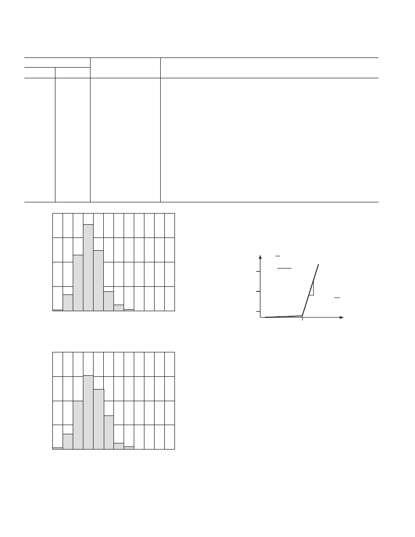
Figure 4. Rise Time Distribution Under Worst-
Case Operating Conditions
FALL TIME – ps
080
C
10
20
30
40
82
84
86
88
90
92
94
96
98
100 102 104
Figure 5. Fall Time Distribution Under Worst-
Case Operating Conditions
GENERAL
Laser diodes have current-in to light-out transfer functions as
shown in Figure 6. Two key characteristics of this transfer function
are the threshold current, I
TH
, and slope in the linear region
beyond the threshold current, referred to as slope efficiency, LI.
ER =
P
AV
=
P1
P0
P1 + P0
2
P
I
LI =
P
I
I
TH
CURRENT
P1
P
AV
P0
O
Figure 6. Laser Transfer Function
Control
A monitor photodiode, MPD, is required to control the LD.
The MPD current is fed into the ADN2847 to control the power
and extinction ratio, continuously adjusting the bias current and
modulation current in response to the laser
’
s changing threshold
current and light-to-current slope efficiency.
The ADN2847 uses automatic power control, APC, to maintain
a constant average power over time and temperature.
The ADN2847 uses closed-loop extinction ratio control to allow
optimum setting of extinction ratio for every device. Thus
SONET/SDH interface standards can be met over device
variation, temperature, and laser aging. Closed-loop modulation
control eliminates the need to either overmodulate the LD or
include external components for temperature compensation.
This reduces research and development time and second
sourcing issues caused by characterizing LDs.
Average power and extinction ratio are set using the PSET and
ERSET pins, respectively. Potentiometers are connected between
these pins and ground. The potentiometer R
PSET
is used to
change the average power. The potentiometer R
is used to
adjust the extinction ratio. Both PSET and ERSET are kept
1.2 V above GND.
PIN FUNCTION DESCRIPTIONS (continued)
Pin Number
48-Lead
32-Lead
Mnemonic
Function
34
35
36
37
38
39
40
41
42
43
44
45
46
47
48
GND2
IDTONE
GND2
GND2
V
CC
2
IMODN
IMODN
GND2
IMODP
IMODP
GND2
GND2
I
BIAS
I
BIAS
CCBIAS
Supply Ground
IDTONE (Requires External Current Sink to Ground)
Supply Ground
Supply Ground
Supply Voltage
Modulation Current Negative Output. Connect via a matching resistor to V
CC
.
Modulation Current Negative Output. Connect via a matching resistor to V
CC
.
Supply Ground
Modulation Current Positive Output. Connect to laser diode.
Modulation Current Positive Output. Connect to laser diode.
Supply Ground
Supply Ground
Laser Diode Bias Current
Laser Diode Bias Current
Extra Laser Diode Bias when AC-Coupled Current Sink
25
26
26
27
28
28
29
30
31
31
32
相關(guān)PDF資料 |
PDF描述 |
|---|---|
| ADN2847ACP-32 | 3 V Dual-Loop 50 Mbps to 3.3 Gbps Laser Diode Driver |
| ADN2847ACP-32-RL | 3 V Dual-Loop 50 Mbps to 3.3 Gbps Laser Diode Driver |
| ADN2847ACP-32-RL7 | 3 V Dual-Loop 50 Mbps to 3.3 Gbps Laser Diode Driver |
| ADN2847ACP-48 | 3 V Dual-Loop 50 Mbps to 3.3 Gbps Laser Diode Driver |
| ADN2847ACP-48-RL | 3 V Dual-Loop 50 Mbps to 3.3 Gbps Laser Diode Driver |
相關(guān)代理商/技術(shù)參數(shù) |
參數(shù)描述 |
|---|---|
| ADN2847ACP-32 | 制造商:Analog Devices 功能描述:Laser Driver DFB 3.3Gbps 1-CH 32-Pin LFCSP EP |
| ADN2847ACP-32-RL | 制造商:Analog Devices 功能描述:Laser Driver DFB 3.3Gbps 1-CH 32-Pin LFCSP EP T/R |
| ADN2847ACP-32-RL7 | 制造商:Analog Devices 功能描述:Laser Driver DFB 3.3Gbps 1-CH 32-Pin LFCSP EP T/R |
| ADN2847ACP-48 | 制造商:Analog Devices 功能描述:Laser Driver DFB 3.3Gbps 1-CH 48-Pin LFCSP EP |
| ADN2847ACP-48-RL | 制造商:Analog Devices 功能描述:Laser Driver DFB 3.3Gbps 1-CH 48-Pin LFCSP EP T/R |
發(fā)布緊急采購(gòu),3分鐘左右您將得到回復(fù)。