- 您現在的位置:買賣IC網 > PDF目錄374039 > ADUC814ARU (ANALOG DEVICES INC) MicroConverter, Small Package 12-Bit ADC with Embedded Flash MCU PDF資料下載
參數資料
| 型號: | ADUC814ARU |
| 廠商: | ANALOG DEVICES INC |
| 元件分類: | 微控制器/微處理器 |
| 英文描述: | MicroConverter, Small Package 12-Bit ADC with Embedded Flash MCU |
| 中文描述: | 8-BIT, FLASH, 16.78 MHz, MICROCONTROLLER, PDSO28 |
| 封裝: | 4.40 X 9.70 MM, MO-153AE, TSSOP-28 |
| 文件頁數: | 28/72頁 |
| 文件大小: | 846K |
| 代理商: | ADUC814ARU |
第1頁第2頁第3頁第4頁第5頁第6頁第7頁第8頁第9頁第10頁第11頁第12頁第13頁第14頁第15頁第16頁第17頁第18頁第19頁第20頁第21頁第22頁第23頁第24頁第25頁第26頁第27頁當前第28頁第29頁第30頁第31頁第32頁第33頁第34頁第35頁第36頁第37頁第38頁第39頁第40頁第41頁第42頁第43頁第44頁第45頁第46頁第47頁第48頁第49頁第50頁第51頁第52頁第53頁第54頁第55頁第56頁第57頁第58頁第59頁第60頁第61頁第62頁第63頁第64頁第65頁第66頁第67頁第68頁第69頁第70頁第71頁第72頁
ADuC814
Rev. A | Page 28 of 72
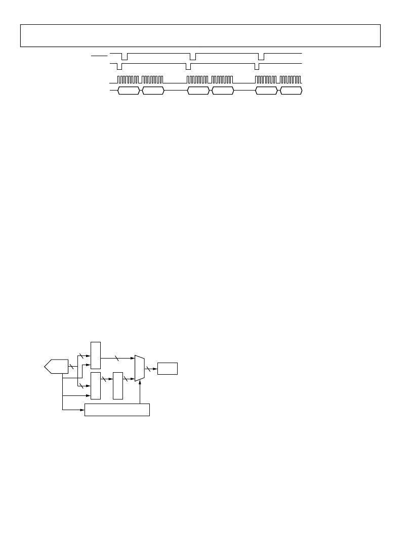
ADCDATAH
ADCDATAL
ADCDATAH
ADCDATAL
ADCDATAH
ADCDATAL
MOSI
SCLOCK
BUSY
CONVST
0
Figure 30. High Speed Data Capture Logic Timing (Pipelined Mode)
In this mode, the ADC to SPI data transfer occurs during the
next ADC conversion. To avoid loss of an ADC result, the user
must ensure that the ADC to SPI transfer rate is complete
before the current ADC conversion ends.
To enable HSDC mode, Bit 6 in ADCCON2 (ADCSPI) must be
set and to enable the ADuC814 to capture a contiguous sample
stream at full ADC update rates (247 kHz).
To configure the ADuC814 in HSDC mode:
1.
The ADC must be put into one of its conversion modes.
2.
The SPI interface must be configured. (The SPI configura-
tion is detailed in the Serial Peripheral Interface section).
3.
Enable HSDC by setting the ADCSPI bit in the ADCCON2
SFR.
4.
Apply trigger signal to the ADC to perform conversions.
Once configured and enabled, the ADC results are transferred
from the ADCDATAH/L SFRs to the SPIDAT register. Figure 31
shows the HSDC logic configuration once the mode is enabled.
The ADC result is transmitted most significant bit first. In this
case, the channel ID is transmitted first, followed by the 12-bit
ADC result. When this mode is enabled, normal SPI and Port 3
operation is disabled; however, the core is free to continue code
execution, including general housekeeping and communication
tasks. This mode is disabled by clearing the ADCSPI bit.
M
SPIDAT
8
8
8
8
16
8
8
0
10
1
ADC TO SPI CONTROL LOGIC
A
A
R
ADC
EDC
SPI LOGIC
DATA
REGISTER
END OF
CONVERSION
SIGNAL
0
Figure 31. High Speed Data Capture Logic
ADC OFFSET AND GAIN CALIBRATION OVERVIEW
The ADC block incorporates calibration hardware and
associated SFRs, which ensures optimum offset and gain
performance from the ADC at all times.
As part of internal factory final test routines, the ADuC814 is
calibrated to its offset and gain specifications. The offset and
gain coefficients obtained from this factory calibration are
stored in non-volatile Flash/EE memory. These are downloaded
from the Flash/EE memory to offset and gain calibration
registers automatically on a power-up or a reset event.
In many applications these factory-generated calibration
coefficients suffice. However, the ADuC814 ADC offset and
gain accuracy may vary from system to system due to board
layout, grounding, clock speed, or system configuration, and so
on. To get the best ADC accuracy in your system, an ADC
calibration should be performed.
Two main advantages are derived from ensuring the ADC
calibration registers are initialized correctly. First, the internal
errors in the ADC can be reduced significantly to give superior
dc performance; and second, system offset and gain errors can
be removed. This allows the user to remove reference errors
(whether an internal or external reference) and to use the full
dynamic range of the ADC by adjusting the analog input range
of the part for a specific system.
ADC OFFSET AND GAIN CALIBRATION
COEFFICIENTS
The ADuC814 has two ADC calibration coefficients, one for
offset calibration and one for gain calibration. Both the offset
and gain calibration coefficients are 14-bit words, and each is
stored in two registers located in the special function register
(SFR) area. The offset calibration coefficient is divided into
ADCOFSH (6 bits) and ADCOFSL (8 bits), and the gain cali-
bration coefficient is divided into ADCGAINH (6 bits) and
ADCGAINL (8 bits).
The offset calibration coefficient compensates for dc offset
errors in both the ADC and the input signal. Increasing the
offset coefficient compensates for positive offset, and effectively
pushes down the ADC transfer function. Decreasing the offset
coefficient compensates for negative offset, and effectively pushes
up the ADC transfer function. The maximum offset that can be
compensated is typically ± 3.5% of V
REF
, which equates to typi-
cally ±87.5 mV with a 2.5 V reference.
Similarly, the gain calibration coefficient compensates for dc
gain errors in both the ADC and the input signal. Increasing the
gain coefficient compensates for a smaller analog input signal
range and scales up the ADC transfer function, effectively
increasing the slope of the transfer function. Decreasing the
相關PDF資料 |
PDF描述 |
|---|---|
| ADUC814ARU-REEL | MicroConverter, Small Package 12-Bit ADC with Embedded Flash MCU |
| ADUC824 | MicroConverter, Dual-Channel 16-/24-Bit ADCs with Embedded FLASH MCU |
| ADUC824BS | MicroConverter, Dual-Channel 16-/24-Bit ADCs with Embedded FLASH MCU |
| ADUC831 | LJT 6C 6#22D PIN RECP |
| ADUC831BCP | Circular Connector; No. of Contacts:6; Series:LJT07R; Body Material:Aluminum; Connecting Termination:Crimp; Connector Shell Size:9; Circular Contact Gender:Socket; Circular Shell Style:Jam Nut Receptacle; Insert Arrangement:9-35 |
相關代理商/技術參數 |
參數描述 |
|---|---|
| ADUC814ARU-D2 | 制造商:Analog Devices 功能描述:12 BIT ADC WITH EMBEDDED 8-BIT MICRO I.C - Tape and Reel 制造商:Rochester Electronics LLC 功能描述:12 BIT ADC WITH EMBEDDED 8-BIT MICRO I.C - Bulk |
| ADUC814ARU-REEL | 制造商:Analog Devices 功能描述:MCU 8-Bit ADuC8xx 8052 CISC 8KB Flash 3V/5V 28-Pin TSSOP T/R 制造商:Analog Devices 功能描述:12 BIT ADC WITH EMBEDDED 8-BIT MICRO I.C - Tape and Reel |
| ADUC814ARU-REEL7 | 制造商:Analog Devices 功能描述:MCU 8-Bit ADuC8xx 8052 CISC 8KB Flash 3V/5V 28-Pin TSSOP T/R 制造商:Analog Devices 功能描述:12 BIT ADC WITH EMBEDDED 8-BIT MICRO I.C - Tape and Reel 制造商:Rochester Electronics LLC 功能描述:12 BIT ADC WITH EMBEDDED 8-BIT MICRO I.C - Tape and Reel |
| ADUC814ARUZ | 功能描述:IC ADC 12BIT W/FLASH MCU 28TSSOP RoHS:是 類別:集成電路 (IC) >> 嵌入式 - 微控制器, 系列:MicroConverter® ADuC8xx 產品培訓模塊:MCU Product Line Introduction XMEGA Introduction AVR XMEGA USB Connectivity 標準包裝:90 系列:AVR® XMEGA 核心處理器:AVR 芯體尺寸:8/16-位 速度:32MHz 連通性:I²C,IrDA,SPI,UART/USART 外圍設備:欠壓檢測/復位,DMA,POR,PWM,WDT 輸入/輸出數:50 程序存儲器容量:192KB(96K x 16) 程序存儲器類型:閃存 EEPROM 大小:4K x 8 RAM 容量:16K x 8 電壓 - 電源 (Vcc/Vdd):1.6 V ~ 3.6 V 數據轉換器:A/D 16x12b; D/A 2x12b 振蕩器型:內部 工作溫度:-40°C ~ 85°C 封裝/外殼:64-TQFP 包裝:托盤 配用:ATSTK600-RC14-ND - STK600 SOCKET/ADAPTER 64TQFPATSTK600-TQFP64-ND - STK600 SOCKET/ADAPTER 64-TQFPATAVRONEKIT-ND - KIT AVR/AVR32 DEBUGGER/PROGRMMRATAVRISP2-ND - PROGRAMMER AVR IN SYSTEM |
| ADUC814ARUZ-REEL | 功能描述:IC MCU FLASH 12BIT ADC 28TSSOP RoHS:是 類別:集成電路 (IC) >> 嵌入式 - 微控制器, 系列:MicroConverter® ADuC8xx 標準包裝:38 系列:Encore!® XP® 核心處理器:eZ8 芯體尺寸:8-位 速度:5MHz 連通性:IrDA,UART/USART 外圍設備:欠壓檢測/復位,LED,POR,PWM,WDT 輸入/輸出數:16 程序存儲器容量:4KB(4K x 8) 程序存儲器類型:閃存 EEPROM 大小:- RAM 容量:1K x 8 電壓 - 電源 (Vcc/Vdd):2.7 V ~ 3.6 V 數據轉換器:- 振蕩器型:內部 工作溫度:-40°C ~ 105°C 封裝/外殼:20-SOIC(0.295",7.50mm 寬) 包裝:管件 其它名稱:269-4116Z8F0413SH005EG-ND |
發(fā)布緊急采購,3分鐘左右您將得到回復。