- 您現在的位置:買賣IC網 > PDF目錄374047 > ADV7302A (Analog Devices, Inc.) 32X2 SHROUDED VERT. HDR PDF資料下載
參數資料
| 型號: | ADV7302A |
| 廠商: | Analog Devices, Inc. |
| 英文描述: | 32X2 SHROUDED VERT. HDR |
| 中文描述: | 多格式統計,逐行掃描/ HDTV視頻編碼器與六11位DAC |
| 文件頁數: | 48/68頁 |
| 文件大小: | 1177K |
| 代理商: | ADV7302A |
第1頁第2頁第3頁第4頁第5頁第6頁第7頁第8頁第9頁第10頁第11頁第12頁第13頁第14頁第15頁第16頁第17頁第18頁第19頁第20頁第21頁第22頁第23頁第24頁第25頁第26頁第27頁第28頁第29頁第30頁第31頁第32頁第33頁第34頁第35頁第36頁第37頁第38頁第39頁第40頁第41頁第42頁第43頁第44頁第45頁第46頁第47頁當前第48頁第49頁第50頁第51頁第52頁第53頁第54頁第55頁第56頁第57頁第58頁第59頁第60頁第61頁第62頁第63頁第64頁第65頁第66頁第67頁第68頁
REV. A
–48–
ADV7302A/ADV7303A
The Digital Noise Reduction Registers are three 8-bit wide
registers. They are used to control the DNR processing.
Coring Gain Border
[Address 63h, Bits 3–0]
These four bits are assigned to the gain factor applied to border
areas. In DNR Mode, the range of gain values is 0
–
1, in incre-
ments of 0.125. This factor is applied to the DNR filter output
that lies below the set threshold range. The result is then sub-
tracted from the original signal.
In DNR Sharpness Mode, the range of gain values is 0 to 0.5, in
increments of 0.0625. This factor is applied to the DNR filter
output that lies above the threshold range. The result is added
to the original signal.
Coring Gain Data
[Address 63h, Bits 7–4]
These four bits are assigned to the gain factor applied to the
luma data inside the MPEG pixel block.
In DNR Mode, the range of gain values is 0
–
1, in increments of
0.125. This factor is applied to the DNR filter output that lies
below the set threshold range. The result is then subtracted
from the original signal.
In DNR Sharpness Mode, the range of gain values is 0
–
0.5, in
increments of 0.0625. This factor is applied to the DNR filter
output that lies above the threshold range. The result is added
to the original signal.
O X X X X X X O O X X X X X X O
O X X X X X X O O X X X X X X O
O X X X X X X O O X X X X X X O
DNR27 – DNR24 = 01HEX
OFFSET CAUSED
BY VARIATIONS IN
INPUT TIMING
APPLY BORDER
CORING GAIN
APPLY DATA
CORING GAIN
Figure 69. DNR Block Offset Control
DNR Threshold
[Address 64h, Bits 5–0]
These six bits are used to define the threshold value in the range
of 0 to 63. The range is an absolute value.
Border Area
[Address 64h, Bit 6]
In setting this bit to a Logic
“
1,
”
the block transition area can
be defined to consist of four pixels. If this bit is set to a Logic
“
0,
”
the border transition area consists of two pixels, where one
pixel refers to two clock cycles at 27 MHz.
720 485 PIXELS
(NTSC)
8 8 PIXEL BLOCK
8 8 PIXEL BLOCK
2 PIXEL
BORDER DATA
Figure 70. DNR Border Area
Block Size Control
[Address 64h, Bit 7]
This bit is used to select the size of the data blocks to be pro-
cessed. Setting the block size control function to a Logic
“
1
”
defines a 16
16 pixel data block, a Logic
“
0
”
defines an 8
pixel data block, where 1 pixel refers to 2 clock cycles at 27 MHz.
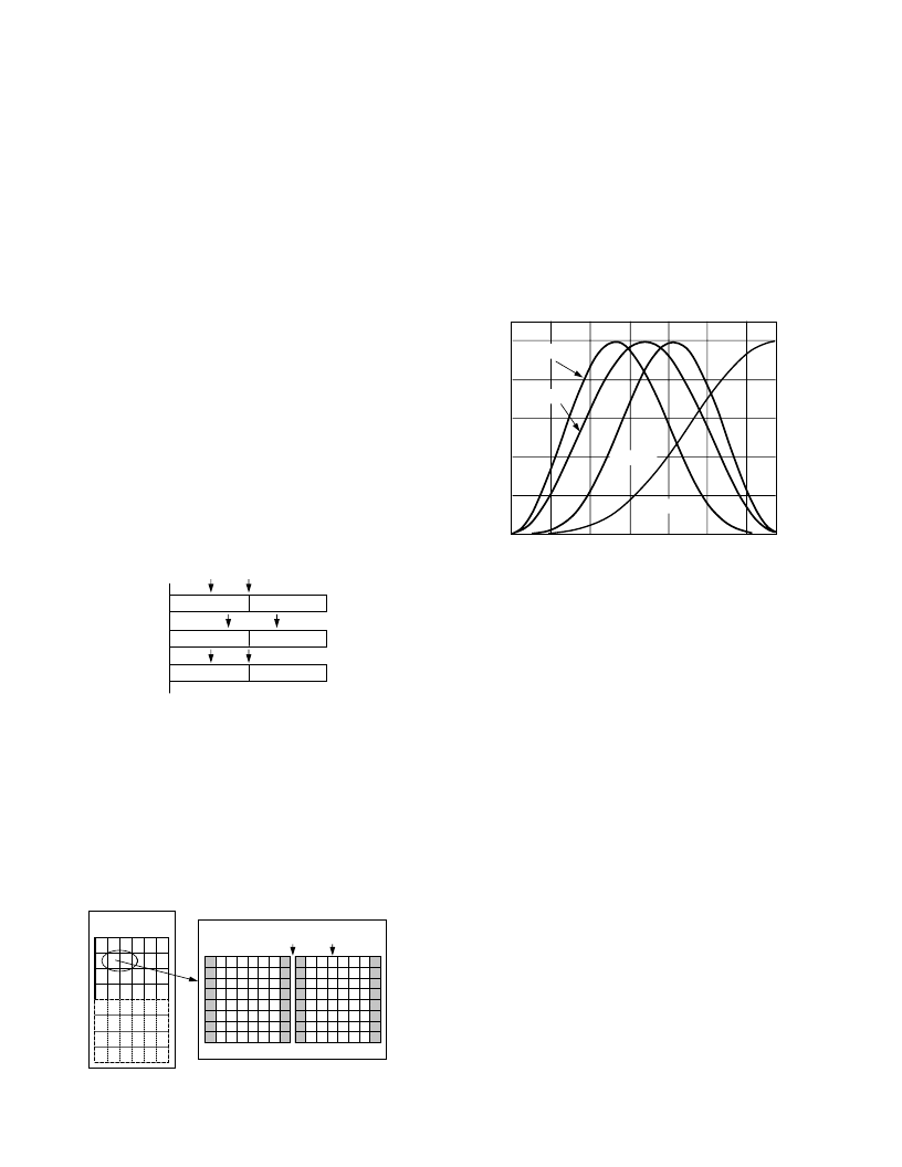
DNR Input Select Control
[Address 65h, Bits 2–0]
Three bits are assigned to select the filter that is applied to the
incoming Y data. The signal that lies in the pass band of the
selected filter is the signal that will be DNR processed. The figure
below shows the filter responses selectable with this control.
8
FILTER C
FILTER B
FILTER A
FILTER D
FREQUENCY – Hz
00
1
2
3
4
5
6
0.2
0.4
0.6
0.8
1.0
Figure 71. DNR Input Select
DNR Mode Control
[Address 65h, Bit 3]
This bit controls the DNR mode selected. A Logic
“
0
”
selects
DNR mode, a Logic
“
1
”
selects DNR Sharpness Mode.
DNR works on the principle of defining low amplitude, high
frequency signals as probable noise and subtracting this noise
from the original signal.
In DNR Mode, it is possible to subtract a fraction of the signal
that lies below the set threshold, assumed to be noise, from the
original signal. The threshold is set in DNR Register 1.
When DNR Sharpness Mode is enabled, it is possible to add a
fraction of the signal that lies above the set threshold to the origi-
nal signal, since this data is assumed to be valid data and not
noise. The overall effect is that the signal will be boosted (similar
to using extended SSAF filter).
Block Offset Control
[Address 65h, Bits 7–4]
Four bits are assigned to this control, which allows a shift of the
data block of 15 pixels maximum. Consider the coring gain posi-
tions fixed. The block offset shifts the data in steps of one pixel
such that the border coring gain factors can be applied at the
same position regardless of variations in input timing of the data.
相關PDF資料 |
PDF描述 |
|---|---|
| ADV7302AKST | Sand Paper; Abrasive Grade:A VFN; Color:Maroon; Pack Quantity:6; Roll Length:30ft; Width:2" |
| ADV7303A | Sand Paper; Abrasive Grade:A VFN; Color:Maroon; Pack Quantity:4; Roll Length:30ft; Width:3" |
| ADV7303AKST | Sand Paper; Abrasive Grade:T; Color:White; Pack Quantity:3; Roll Length:30ft; Width:4" |
| ADV7310 | Multiformat 216 MHz Video Encoder with Six NSV 12-Bit DACs |
| ADV7310KST | Multiformat 216 MHz Video Encoder with Six NSV 12-Bit DACs |
相關代理商/技術參數 |
參數描述 |
|---|---|
| ADV7302AKST | 制造商:AD 制造商全稱:Analog Devices 功能描述:Multiformat SD, Progressive Scan/HDTV Video Encoder with Six 11-Bit DACs |
| ADV7303A | 制造商:AD 制造商全稱:Analog Devices 功能描述:Multiformat SD, Progressive Scan/HDTV Video Encoder with Six 11-Bit DACs |
| ADV7303AKST | 制造商:Rochester Electronics LLC 功能描述:150MHZ HD 108MHZ PROG SCAN 11BIT ENC I.C - Bulk 制造商:Analog Devices 功能描述: |
| ADV73045701 | 制造商:LG Corporation 功能描述:Frame Assembly |
| ADV73045702 | 制造商:LG Corporation 功能描述:Frame Assembly |
發布緊急采購,3分鐘左右您將得到回復。