- 您現在的位置:買賣IC網 > PDF目錄379664 > AM79231 (Electronic Theatre Controls, Inc.) Intelligent Subscriber Line Interface Circuit (ISLIC) PDF資料下載
參數資料
| 型號: | AM79231 |
| 廠商: | Electronic Theatre Controls, Inc. |
| 英文描述: | Intelligent Subscriber Line Interface Circuit (ISLIC) |
| 中文描述: | 智能用戶線接口電路(ISLIC) |
| 文件頁數: | 14/28頁 |
| 文件大小: | 278K |
| 代理商: | AM79231 |
第1頁第2頁第3頁第4頁第5頁第6頁第7頁第8頁第9頁第10頁第11頁第12頁第13頁當前第14頁第15頁第16頁第17頁第18頁第19頁第20頁第21頁第22頁第23頁第24頁第25頁第26頁第27頁第28頁

14
Am79231 Data Sheet
Thermal Resistance
The junction to air thermal resistance of the Am79231 in a 32-pin, PLCC package is 45
°
C/W. The
typical junction to case thermal resistance is 14
°
C/W. Measured under free air convection conditions
and without external heatsinking.
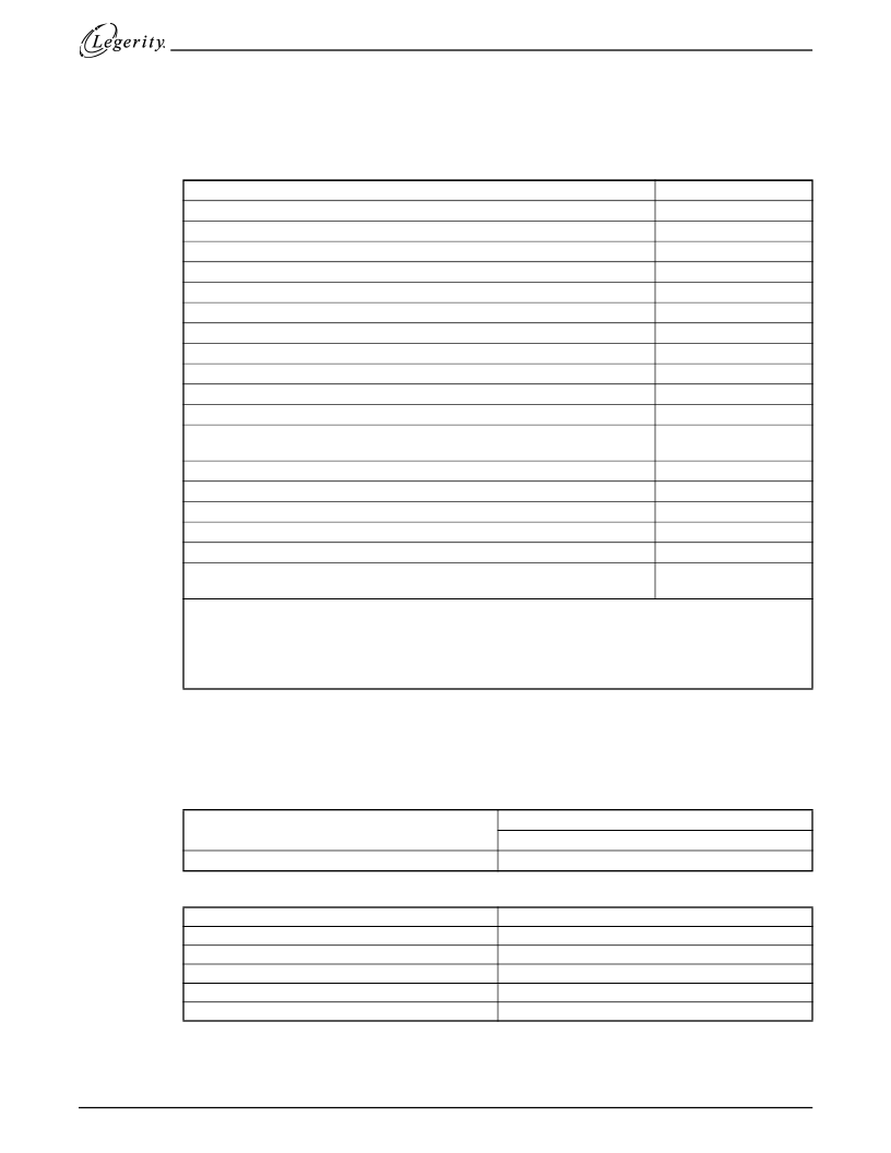
Absolute Maximum Ratings
Operating Ranges
Operating ranges define those limits between which device functionality is guaranteed. Functionality
of the device from 0
°
C to 70
°
C is guaranteed by production testing. Performance from
–
40
°
C to
85
°
C is guaranteed by characterization and periodic sampling of production units.
Environmental Ranges
Electrical Maximum Ranges
Note:
Vloopmax: Maximum expected loop voltage in application; I
LOOP
maximum off-hook loop resistance.
Vpk:
Peak signal voltage for application.
Storage temperature
Ambient temperature, under bias
Humidity
VCC with respect to GND
VBH, VBL with respect to GND
2
BGND with respect to GND
Voltage on relay outputs
AD or BD to BGND:
Continuous
10 ms (F = 0.1 Hz)
1 μs (F = 0.1 Hz)
250 ns (F = 0.1 Hz)
Current into SA or SB: 10 μs rise to Ipeak; 1000 μs fall to 0.5 Ipeak;
2000 μs fall to I =0
Current into SA or SB: 2 μs rise to Ipeak; 10 μs fall to 0.5 Ipeak; 20 μs fall to I = 0
SA SB continuous
Current through AD or BD
P1, P2, P3, LD to GND
ESD Immunity (Human Body Model)
Maximum power dissipation,
1
T
A
= 70
°
C
T
A
= 85
°
C
Notes:
1. Thermal limiting circuitry on chip will shut down the circuit at a junction temperature of about 165
°
C. The
device should never see this temperature. Operation above 145
°
C junction temperature may degrade
device reliability.
2. Rise time of VBH (dv/dt) must be limited to less than 27 v/
μ
s.
–
55 to +150
°
C
–
40 to +85
°
C
TBD
–
0.4 to +7 V
+0.4 to
–
70 V
–
3 to +3 V
+7 V
VBH
–
1 to BGND + 1
VBH
–
5 to BGND + 5
VBH
–
10 to BGND + 10
VBH
–
15 to BGND + 15
Ipeak = ±5 mA
Ipeak = ±12.5 mA
5 mA
± 150 mA
–
0.4 to VCC + 0.4 V
1500 V min
1.67 W
1.33 W
Ambient Temperature
0 to 70
°
C Commercial
–
40 to +85
°
C extended temperature
15 to 85%
Ambient Relative Humidity
VCC
VBL
VBH
BGND with respect to GND
Load resistance on VTX to Vref
Load resistance on VSAB to Vref
5 V ± 5%
–
(Vloopmax + 6V + Vpk) to VBH V
–
42.5 V to
–
70 V
–
100 mV to +100 mV
20 k
minimum
20 k
minimum
相關PDF資料 |
PDF描述 |
|---|---|
| AM79231JC | Intelligent Subscriber Line Interface Circuit (ISLIC) |
| AM8127LTB | AM8127 Clock Generator |
| AMZ8127 | AM8127 Clock Generator |
| AM8127XTB | AM8127 Clock Generator |
| AM8127 | AM8127 Clock Generator |
相關代理商/技術參數 |
參數描述 |
|---|---|
| AM79231JC | 制造商:未知廠家 制造商全稱:未知廠家 功能描述:Intelligent Subscriber Line Interface Circuit (ISLIC) |
| AM7924JC | 制造商:未知廠家 制造商全稱:未知廠家 功能描述:Subscriber Line Interface Circuit |
| AM7924SC | 制造商:未知廠家 制造商全稱:未知廠家 功能描述:Telecommunication IC |
| AM7926-1VC | 制造商:未知廠家 制造商全稱:未知廠家 功能描述:Telecommunication IC |
| AM7926-2VC | 制造商:未知廠家 制造商全稱:未知廠家 功能描述:Telecommunication IC |
發布緊急采購,3分鐘左右您將得到回復。