- 您現在的位置:買賣IC網 > PDF目錄379664 > AM79231 (Electronic Theatre Controls, Inc.) Intelligent Subscriber Line Interface Circuit (ISLIC) PDF資料下載
參數資料
| 型號: | AM79231 |
| 廠商: | Electronic Theatre Controls, Inc. |
| 英文描述: | Intelligent Subscriber Line Interface Circuit (ISLIC) |
| 中文描述: | 智能用戶線接口電路(ISLIC) |
| 文件頁數: | 15/28頁 |
| 文件大小: | 278K |
| 代理商: | AM79231 |
第1頁第2頁第3頁第4頁第5頁第6頁第7頁第8頁第9頁第10頁第11頁第12頁第13頁第14頁當前第15頁第16頁第17頁第18頁第19頁第20頁第21頁第22頁第23頁第24頁第25頁第26頁第27頁第28頁
Am79231 Data Sheet
15
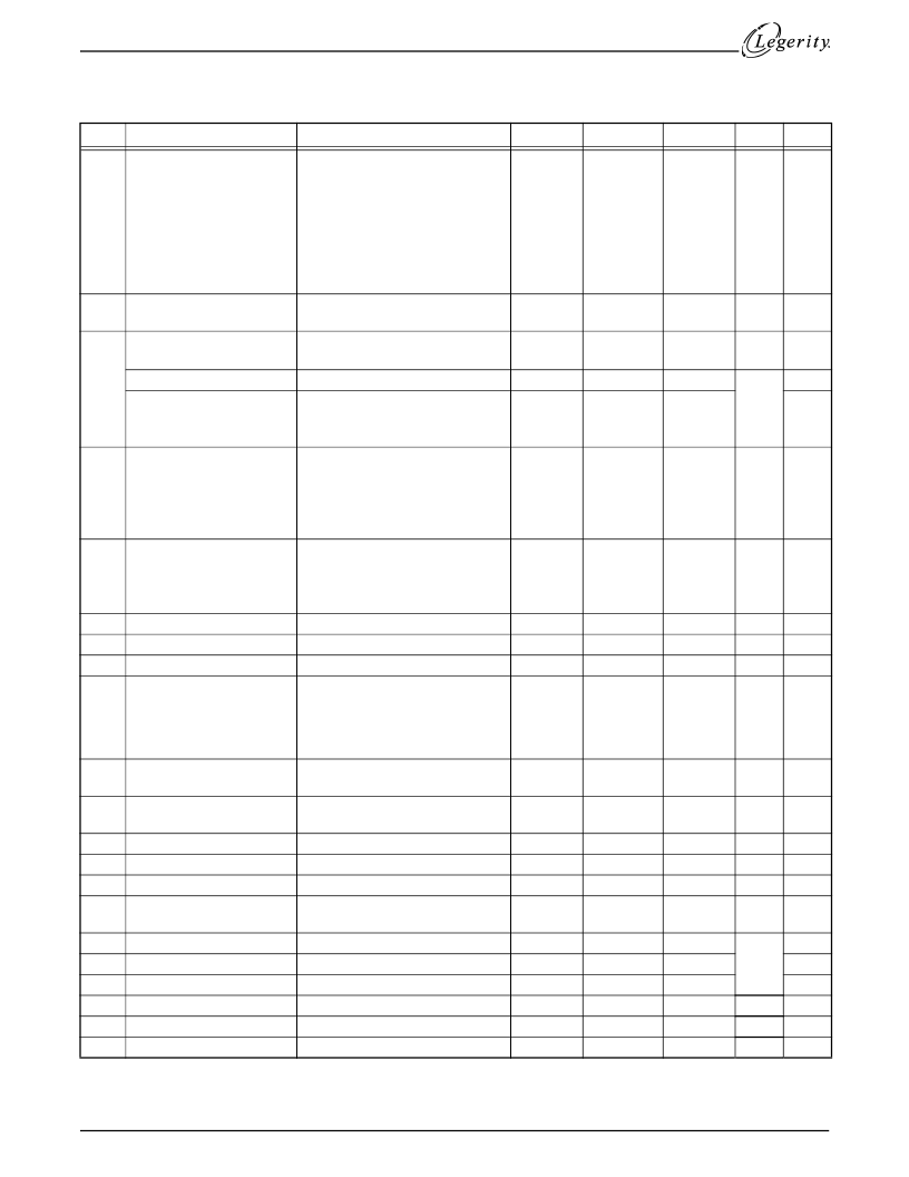
SPECIFICATIONS
Target Specifications (See note 1)
No.
Item
Condition
Min
Typ
Max
Unit
Note
1
Two-wire loop voltage (in-
cluding offset)
Standby mode, open circuit,
|VBH| < 55 V
|VBH| > 55 V
Any Active mode (does not
include OHT),
RL = 600
, I
RSN
= 50
μ
A
OHT mode, RL = 600
I
RSN
= 20
μ
A
VBH
–
8
48
13.88
8.64
19.8
130
VBH
–
7
51
15
10.8
22
250
VBH
–
6
55.5
16.13
12.96
V
3
2
Feed resistance per leg at
pins AD & BD
Feed current limit
Standby mode
375
3
Feed current
Standby mode, RL = 600
Standby mode, RL = 2200
Standby mode
A to VBH
B to Ground
Low boundary
High boundary
Input high current
Input low current
Mid-level current
Input high voltage
Input low voltage
Input high current
Input low current
34
56
45
mA
IMT current
ILG current
44.6
μA
36
43
4
Ternary input voltage
boundaries for LD pin.
Mid-level input source
must be Vref.
CREF
–
1
108
47
51
0.6
V
V
μA
μA
μA
V
V
μA
μA
mV
mA
mA
—
—
—
—
3
5
Logic Inputs P1, P2, P3
2.0
10
50
0.8
6
7
8
9
VTX output offset
VREF input current
CREF input current
β
, DC Ratio of VSAB to
loop voltage:
V
V
SA
–
–
50
+50
VREF = 1.4 V
CREF = 3.3 V
Tj < 145
°
C, VSA
–
VSB = 22 V
.05
.09
3
3
0.0088
0.0097
0.0106
V/V
10
Fault Indicator Threshold
Voltage Output on IMT
TBD
CREF -
0.3 V
30
CREF
V
3
11
Gain from VLB pin to A or
B pin
VLB pin input current
ILOOP/IMT
ILONG/ILG
Input current, SA and SB
pins
K1
ISA/IMT
ISB/ILG
VSAB output offset
IMT output offset
ILG output offset
V/V
12
13
14
15
VLB = VREF
±
1 V
ILOOP = 10 mA
ILONG = 10 mA
Active modes
TBD
300
600
1.0
mA
A/A
A/A
275
560
325
640
3.0
μA
3
16
17
18
19
20
21
Incremental DC current gain
Disconnect, ISA = 2 mA
Disconnect, ISB = 2 mA
500
6
12
TBD
0
1
A/A
mV
mV
mV
-3
-1
3
3
β
V
SB
-----------------------
=
相關PDF資料 |
PDF描述 |
|---|---|
| AM79231JC | Intelligent Subscriber Line Interface Circuit (ISLIC) |
| AM8127LTB | AM8127 Clock Generator |
| AMZ8127 | AM8127 Clock Generator |
| AM8127XTB | AM8127 Clock Generator |
| AM8127 | AM8127 Clock Generator |
相關代理商/技術參數 |
參數描述 |
|---|---|
| AM79231JC | 制造商:未知廠家 制造商全稱:未知廠家 功能描述:Intelligent Subscriber Line Interface Circuit (ISLIC) |
| AM7924JC | 制造商:未知廠家 制造商全稱:未知廠家 功能描述:Subscriber Line Interface Circuit |
| AM7924SC | 制造商:未知廠家 制造商全稱:未知廠家 功能描述:Telecommunication IC |
| AM7926-1VC | 制造商:未知廠家 制造商全稱:未知廠家 功能描述:Telecommunication IC |
| AM7926-2VC | 制造商:未知廠家 制造商全稱:未知廠家 功能描述:Telecommunication IC |
發布緊急采購,3分鐘左右您將得到回復。