- 您現在的位置:買賣IC網 > PDF目錄375831 > FLL2400IU-2C (FUJITSU LTD) L-Band High Power GaAs FET PDF資料下載
參數資料
| 型號: | FLL2400IU-2C |
| 廠商: | FUJITSU LTD |
| 元件分類: | 功率晶體管 |
| 英文描述: | L-Band High Power GaAs FET |
| 中文描述: | L BAND, GaAs, N-CHANNEL, RF POWER, JFET |
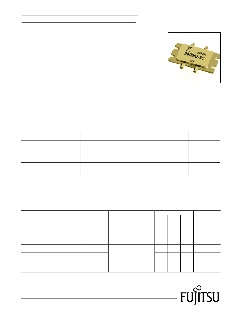
| 封裝: | CASE IU, 6 PIN |
| 文件頁數: | 1/4頁 |
| 文件大小: | 105K |
| 代理商: | FLL2400IU-2C |
1
Edition 1.0 Preliminary
November 2000
FLL2400IU-2C
L-Band High Power GaAs FET
DESCRIPTION
The FLL2400IU-2C is a 240 Watt GaAs FET that employs a push-pull design that
offers ease of matching, greater consistency and a broader bandwidth for high
power L-band amplifiers. This product is targeted to reduce the size and
complexity of highly linear, high power base station transmitting amplifiers.
This new product is well suited for use in W-CDMA and IMT 2000 base station
amplifiers as it offers high gain, long term reliability and ease of use.
FEATURES
Push-Pull Configuration
High Power Output: 240W (Typ.)
Broad Frequency Range: 2100 to 2200 MHz.
Suitable for class AB operation.
APPLICATIONS
Solid State Base-Station Power Amplifier.
W-CDMA and IMT 2000 Communication Systems.
Item
Symbol
VDS = 12V
f = 2.17 GHz
IDS = 6.0A
Pin = 45.0dBm
Note 1
Drain Current
I
DSS
-
32
-
V
DS
= 5V, V
GS
= 0V
A
Pinch-Off Voltage
-0.1
-0.3
-0.5
V
DS
= 5V, I
DS
= 680mA
V
V
p
-5
Gate-Source Breakdown Voltage
V
GSO
-
-
I
GS
= -6.8mA
V
Output Power
52.8
53.8
-
dBm
P
out
Linear Gain
10.5
11.5
-
dB
GL
Thermal Resistance
CASE STYLE: IU
Note 1: The RF test are performed using a P.W. = 1msec., Duty Cycle = 20%
-
0.45
0.65
Channel to Case
°
C/W
R
th
Conditions
Unit
Limits
Typ.
Max.
Min.
ELECTRICAL CHARACTERISTICS (Case Temperature Tc=25
°
C)
Item
Drain-Source Voltage
Gate-Source Voltage
Total Power Dissipation
Storage Temperature
Channel Temperature
Symbol
V
DS
V
GS
P
T
T
stg
Tc = 25
°
C
V
V
W
°
C
°
C
T
ch
Condition
230
-65 to +175
+175
-5
15
Rating
Unit
ABSOLUTE MAXIMUM RATINGS (Ambient Temperature Ta=25
°
C)
Fujitsu recommends the following conditions for the reliable operation of GaAs FETs:
1. The drain-source operating voltage (VDS) should not exceed 12 volts.
2. The forward and reverse gate currents should not exceed 367 and -161 mA respectively with
gate resistance of 1.5
.
3. The operating channel temperature (Tch) and case temperature (Tc) should not exceed 145
°
C and 80
°
C respectively.
相關PDF資料 |
PDF描述 |
|---|---|
| FLL351ME | L-band medium & high power gaas FTEs |
| FLL357ME | L-Band Medium & High Power GaAs FET |
| FLL400IK-2C | High Voltage - High Power GaAs FET |
| FLL400IP-2 | L-Band Medium & High Power GaAs FET |
| FLL410IK-3C | L-Band High Power GaAs FET |
相關代理商/技術參數 |
參數描述 |
|---|---|
| FLL300IL-1 | 制造商:EUDYNA 制造商全稱:Eudyna Devices Inc 功能描述:L-Band Medium & High Power GaAs FET |
| FLL300IL-2 | 制造商:EUDYNA 制造商全稱:Eudyna Devices Inc 功能描述:L-Band Medium & High Power GaAs FET |
| FLL300IL-3 | 制造商:SUMITOMO ELECTRIC Device Innovations Inc 功能描述:L-Band Power GaAs FET(44.5dBm@2.6GHz), Bulk |
| FLL300IP-4 | 制造商:FUJITSU 功能描述: |
| FLL310IQ-3A | 制造商:FUJITSU 功能描述: |
發布緊急采購,3分鐘左右您將得到回復。