- 您現在的位置:買賣IC網 > PDF目錄385353 > HC-5502X (Intersil Corporation) () PDF資料下載
參數資料
| 型號: | HC-5502X |
| 廠商: | Intersil Corporation |
| 英文描述: | () |
| 中文描述: | () |
| 文件頁數: | 10/17頁 |
| 文件大小: | 255K |
| 代理商: | HC-5502X |
4-10
The Ring Command (RC) input is taken low during ringing.
This activates the ring relay driver (RR) output providing the
telephone is not off-hook or the line is not in a power denial
state. The ring relay connects the ring generator to the
subscriber loop. The ring generator output is usually an
80V
RMS
, 20Hz signal. For use with the Intersil SLIC, the ring
signal should not exceed 150V peak. Since the telephone
ringer is AC coupled only ring current will flow. For the HC-
5502X SLIC, the ring current is sunk by the ring feed
amplifier output stage whereas for the HC-5504X the ring
path flows directly into V
B-
via a set of relay contacts. The
high impedance terminal RFS exists on the HC-5504X so
that the low impedance R
F
node can be isolated from the hot
end of the ring path in the battery referenced ring scheme.
The AC ring current flowing in the subscriber circuit will be
sensed across RB4, and will give rise to an AC voltage at the
output of the longitudinal amplifier. R20 and C4 attenuate
this signal before it reaches the ring trip detector to prevent
false ring trip. C4 is nominally set at 0.47
μ
F but can be
increased towards 1
μ
F for short lines or if several
telephones are connected in parallel across the line in order
to prevent false or intermittent ring trip.
When the subscriber goes off-hook, a DC path is established
between the output winding of the ring generator and the
battery ground or V
B-
terminal. A DC longitudinal imbalance
is established since no tip feed current is flowing through the
tip feed resistors. The longitudinal amplifier output is driven
negative. Once it exceeds the ring trip threshold of the ring
trip detector, the logic circuitry is driven by GK to trip the ring
relay establishing an off-hook condition such that SHD will
become active as loop metallic current starts to flow.
In addition to its ability to be used for tip or ring injected
systems, the HC-5504 can also be configured for systems
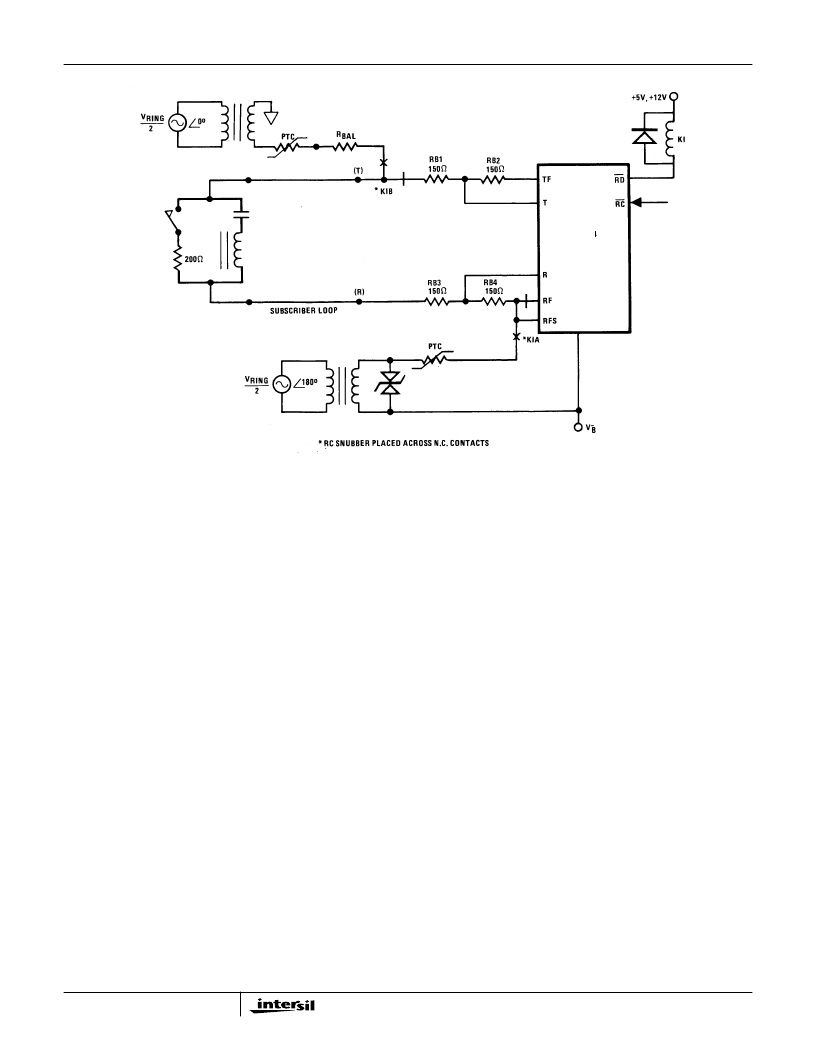
utilizing balanced ringing. Figure 12 shows such an
application. The main advantage of balanced ringing is that it
tends to minimize cross coupling effects owing to the
differential nature of the ring tone across the line.
Figure 13 illustrates the sequence of events during ring trip
with ring synchronization for a tip injected ring system. Note,
that owing to the 90
o
phase shift introduced by the low pass
filter (R20, C4) the RS pulse will occur at the most negative
point of the attenuated ring signal that is fed into the ring trip
detector. Hence, when DC conditions are established for
RTD, the AC component actually assists ring trip taking
place. For a ring side injected ring system, the RS pulse
should occur at the positive zero crossing of the ring signal
as it appears at RFS. If ring synchronization is not used,
then the RS pin should be held permanently to a logic high
of 5V nominally: ring trip will occur asynchronously with
respect to the ring voltage. Ring trip is guaranteed to take
place within three ring cycles after the telephone going off-
hook.
It is recommended that an RC snubber network is placed
across the ring relay contacts to minimize inductive kick-
back effects from the telephone ringer. Typical values for
such a network are shown in Figure 9.
FIGURE 12. HC-5504X BALANCED RINGING CONFIGURATION
HC-5504X
Application Note 549
相關PDF資料 |
PDF描述 |
|---|---|
| HC-5509A1 | SLIC Subscriber Line Interface Circuit |
| HC4P5509A1-9 | SLIC Subscriber Line Interface Circuit |
| HC4P5509A1-5 | SLIC Subscriber Line Interface Circuit |
| HC1-5509A1-5 | SLIC Subscriber Line Interface Circuit |
| HC3-5509A1-5 | SLIC Subscriber Line Interface Circuit |
相關代理商/技術參數 |
參數描述 |
|---|---|
| HC5503 | 制造商:INTERSIL 制造商全稱:Intersil Corporation 功能描述:Low Cost 24V SLIC For PABX / Key Systems |
| HC5503C | 制造商:INTERSIL 制造商全稱:Intersil Corporation 功能描述:Unbalanced PBX/Key System SLIC, Subscriber Line Interface Circuit |
| HC5503CB | 制造商:Rochester Electronics LLC 功能描述: 制造商:Intersil Corporation 功能描述: |
| HC5503CB96 | 制造商:Rochester Electronics LLC 功能描述:HC5503CB (TAPE&REEL) - Bulk |
| HC5503CBZ | 功能描述:電信線路管理 IC LW COST ISDN SLIC 24S0 RoHS:否 制造商:STMicroelectronics 產品:PHY 接口類型:UART 電源電壓-最大:18 V 電源電壓-最小:8 V 電源電流:30 mA 最大工作溫度:+ 85 C 最小工作溫度:- 40 C 安裝風格:SMD/SMT 封裝 / 箱體:VFQFPN-48 封裝:Tray |
發布緊急采購,3分鐘左右您將得到回復。