- 您現在的位置:買賣IC網 > PDF目錄385355 > HCA600ACREF (Intersil Corporation) 600W/1000W Full Bandwidth Class D Amplifier PDF資料下載
參數資料
| 型號: | HCA600ACREF |
| 廠商: | Intersil Corporation |
| 英文描述: | 600W/1000W Full Bandwidth Class D Amplifier |
| 中文描述: | 600W/1000W全帶寬D類放大器 |
| 文件頁數: | 2/11頁 |
| 文件大小: | 351K |
| 代理商: | HCA600ACREF |
2
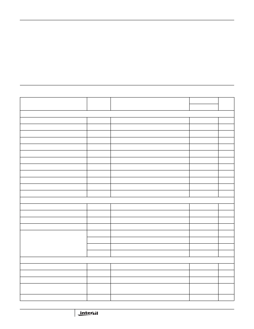
Absolute Maximum Ratings
Operating Conditions
Bus Voltage, V
BUS
. . . . . . . . . . . . . . . . . . . . . . . . . . . . . ±
130V (Note 1)
+/-12V . . . . . . . . . . . . . . . . . . . . . . . . . . . . . . . . . . . . . . . . . . +/-15V
12VFLT. . . . . . . . . . . . . . . . . . . . . . . . . . . . . . . . . . . . . . . -Bus+15V
Audio Inputs. . . . . . . . . . . . . . 12V Differential Peak to Peak Voltage
NOTE:
1. WARNING: The voltages inside the shield, at the
edge connector, and on the speaker cables are
potentially deadly. Extreme caution is required.
Bus Voltage, V
BUS
. . . . . . . . . . . . . . . . . . . . . . . . . . . . . . . . . . . . . ±
110V
+/-12V . . . . . . . . . . . . . . . . . . . . . . . . . . . . . . . . . . . . . . . . . . +/-12V
12VFLT . . . . . . . . . . . . . . . . . . . . . . . . . . . . . . . . . . . . . . -Bus +12V
Ambient Temperature Range. . . . . . . . . . . . . . . . . . . . . 0
o
C to 50
o
C
CAUTION: Stresses above those listed in “Absolute Maximum Ratings” may cause permanent damage to the device. This is a stress only rating and operation of the
device at these or any other conditions above those indicated in the operational sections of this specification is not implied.
Electrical Specifications
R
LOAD
= 8
, V
BUS
=
±
110V, Supply Source Resistance < 2.5
, Storage Capacitor > 12,000
μ
F, 12VFLT = 12V,
+/-12V = +/-12V
PARAMETER
SYMBOL
TEST CONDITIONS
T
A
= 25
o
C
UNITS
TYP
SUPPLY SPECIFICATION
Minimum Bus Voltage
V
BUS MIN
600W into 8
±
110
V
±
V
BUS
RMS Current
I
V BUS
1kHz Sine Wave, Full Output Power (8
load)
3
A
±
V
BUS
RMS Current
I
V BUS
1kHz Sine Wave, Full Output Power (4
load)
6
A
±
V
BUS,Q
Average Current
I
VBUSQ
Quiescent Current, No Signal
60
mA
12V Float Current
I
12VFLTBIAS
Current supplied to power output gate driver circuitry
400
mA
Minimum +/-12V
V
BIASmin
1kHz Sine Wave, Full Output Power (8
load)
11.5
V
±
12V Max RMS Current
I+/-
15V
No input signal
40
mA
Rising Under Voltage Lock Out Voltage
V
UV Rising
Bus voltage that activates the amplifier
±
75
V
Falling Under Voltage Lock Out Voltage
V
UV Falling
Bus voltage that shuts down the amplifier
±
50
V
ENABLE Threshold Voltage
V
ENABLE1
Amplifier starts at this voltage, input amplifier muted
1
V
ENABLE Threshold Voltage
V
ENABLE2
Input amplifiers active and entire amplifier active
2
V
ENABLE Internal Source Current
I
ENABLE
Internal “Pull Up” Current
25
μ
A
OUTPUT POWER AND EFFICIENCY
Maximum Output Power (Note 2)
P
MAX8
THD = 1%, 1kHz, R
LOAD
= 8
600
W
Maximum Output Power (Note 2)
10% THD
8
THD = 10%, 1kHz, R
LOAD
= 8
800
W
Maximum Output Power (Note 2)
P
MAX4
THD = 1%, 1kHz, R
LOAD
= 4
1000
W
Maximum Output Power (Note 2)
10% THD
4
THD = 10%, 1kHz, R
LOAD
= 4
1200
W
Efficiency
PMAX
EFF
P
OUT
= 200W, 8
88
%
PMAX
EFF
P
OUT
= 500W, 8
95
%
PMAX
EFF
P
OUT
= 400W, 4
88
%
PMAX
EFF
P
OUT
= 1000W, 4
90
%
AMPLIFIER PERFORMANCE
Total Harmonic Distortion + Noise
THD+N
P
OUT
= 400W, R
LOAD
= 8
, 1kHz
0.015
%
Signal to Noise Ratio
V
SNR
Relative to full scale output, 600W into 8
110
dB
Output Noise
V
N
200
μ
V
Intermodulation Distortion
IMD
SMPTE, 60Hz and 7kHz, 4:1,
R
LOAD
= 8
at 25W Output
0.02
%
PSRR (
V
OUT
/
V
BUS
)
PSRR
DC
300
μ
V/V
HCA600ACREF
相關PDF資料 |
PDF描述 |
|---|---|
| HCD17010.0MHz | 12V OCXO Sine Output |
| HCD71 | 12V OCXO Sine Output |
| HCD710 | 12V OCXO Sine Output |
| HCD7110.0MHz | 12V OCXO Sine Output |
| HCD170 | OCXO Sine Output |
相關代理商/技術參數 |
參數描述 |
|---|---|
| HCA6306 | 制造商:未知廠家 制造商全稱:未知廠家 功能描述:ASIC |
| HCA6312 | 制造商:未知廠家 制造商全稱:未知廠家 功能描述:ASIC |
| HCA6324 | 制造商:未知廠家 制造商全稱:未知廠家 功能描述:ASIC |
| HCA6348 | 制造商:未知廠家 制造商全稱:未知廠家 功能描述:ASIC |
| HCA6AC0187-05AI | 制造商:TE Connectivity 功能描述: |
發布緊急采購,3分鐘左右您將得到回復。