- 您現(xiàn)在的位置:買賣IC網(wǎng) > PDF目錄30725 > LA7615 SPECIALTY CONSUMER CIRCUIT, PDIP64 PDF資料下載
參數(shù)資料
| 型號(hào): | LA7615 |
| 元件分類: | 消費(fèi)家電 |
| 英文描述: | SPECIALTY CONSUMER CIRCUIT, PDIP64 |
| 封裝: | SDIP-64 |
| 文件頁數(shù): | 13/39頁 |
| 文件大小: | 206K |
| 代理商: | LA7615 |
第1頁第2頁第3頁第4頁第5頁第6頁第7頁第8頁第9頁第10頁第11頁第12頁當(dāng)前第13頁第14頁第15頁第16頁第17頁第18頁第19頁第20頁第21頁第22頁第23頁第24頁第25頁第26頁第27頁第28頁第29頁第30頁第31頁第32頁第33頁第34頁第35頁第36頁第37頁第38頁第39頁
No. 5841-20/39
LA7615
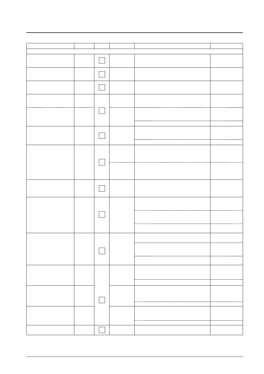
(Test Conditions)
Parameter
Symbol
Test point
Input signal
Test procedure
Bus bits/input signal
[Video Block]
Overall video gain (at maximum
contrast)
Contrast adjustment
characteristics (normal/max)
Contrast adjustment
characteristics (normal/max)
Video frequency characteristics
f0 = 1 (sharp 0)
f0 = 3 (sharp 15)
Chrominance trap level
f0 = 0 (sharp 0)
DC restoration
Luminance delay f0 = 1
Maximum black stretch gain
Black stretch threshold
black(40 IRE black)
Sharpness (peaking) variability
characteristics
(normal)
(maximum)
(minimum)
Horizontal/vertical blanking
output level
CONT63
CONT32
CONT0
Yf03
Ctrap
ClampG
YDLY
BKSTmax
BKSTTH
Sharp16
Sharp31
Sharp0
RGBBLK
L-50
L-CW
L-0
L-100
L-50
L-BK
L-40
L-CW
L-100
Measure the output signal 50 IRE amplitude (CNTHB
Vp-p) and calculate CONT63 = 20log(CNTHB/0.357).
Measure the output signal 50 IRE amplitude (CNTCB
Vp-p) and calculate CONT32 = 20log(CNTCB/0.357).
Measure the output signal 50 IRE amplitude (CNTLB
Vp-p) and calculate CONT0 = 20log(CNTLB/0.357).
With the input signal CW = 100 kHz, measure the
amplitude of the CW signal in the output signal
(PEAKDC Vp-p).
With the input signal CW = 10 MHz, measure the
amplitude of the CW signal in the output signal
(F03 Vp-p).
Calculate Yf3 = 20log(F03/PEAKDC).
With the input signal CW = 3.58 MHz, measure the
amplitude of the CW signal in the output signal
(F00 Vpp).
Calculate Ctrap = 20log(F00/PEAKDC).
Measure the output signal 0 IRE DC level
(BRTPL (V)).
Measure the output signal 0 IRE DC level (DRVPH
(V)) and the 100 IRE amplitude (DRVH Vpp).
Calculate
ClampG = 100
× (1 + (DRVPH – BRTPL)/DRVH)).
Measure the time difference (amount of delay)
between the rise of the input signal 50 IRE
amplitude, and rise of the output signal 50 IRE
amplitude.
Measure the 0 IRE DC level at point A in the output
signal when the black stretch function is defeated
(black stretch off). (BKST1 (V))
Measure the 0 IRE DC level at point A in the output
signal when the black stretch function is on.
(BKST2 (V))
Calculate
BKSTmax = 2
× 50 × (BKST1 – BKST2)/CNTHB.
Measure the 40 IRE DC level in the output signal
when the black stretch function is on. (BKST3 (V))
Measure the 40 IRE DC level in the output signal
when the black stretch function is defeated
(black stretch off). (BKST4 (V))
Calculate
BKSTTH = 50 × (BKST4 – BKST3)/CNTHB.
With the input signal CW = 2.2 MHz, measure the
amplitude of the CW signal in the output signal
(F00S16 Vp-p).
Calculate Sharp16 = 20log(F00S16/PEAKDC).
With the input signal CW = 2.2 MHz, measure the
amplitude of the CW signal in the output signal
(F00S31 Vp-p).
Calculate Sharp31 = 20log(F00S31/PEAKDC).
With the input signal CW = 2.2 MHz, measure the
amplitude of the CW signal in the output signal
(F00S0 Vp-p).
Calculate Sharp0 = 20log(F00S0/PEAKDC).
Measure the DC level of the output signal during the
blanking period (RGBBLK (V)).
TR24: Contrast
111111
TR24: Contrast
000000
TR26: F0 Adjust 01
TR26: F0 Adjust 11
TR25: Sharpness
01111
TR26: F0 Adjust 00
TR23: Brightness
000000
TR24: Contrast
111111
TR23: Brightness
000000
TR24: Contrast
111111
TR31: BKST Defeat
1
TR31: BKST Defeat
0
TR31: BKST Defeat
0
TR31: BKST Defeat
1
TR26: F0 Adjust 00
TR25: Sharpness
10000
TR25: Sharpness
11111
TR25: Sharpness
00000
38
Continued on next page.
相關(guān)PDF資料 |
PDF描述 |
|---|---|
| LA7621 | HORIZ/VERT DEFLECTION IC, PDIP30 |
| LA7620 | HORIZ/VERT DEFLECTION IC, PDIP30 |
| LA7625 | SPECIALTY CONSUMER CIRCUIT, PDIP30 |
| LA7626 | SPECIALTY CONSUMER CIRCUIT, PDIP30 |
| LA7629 | HORIZ/VERT DEFLECTION IC, PDIP30 |
相關(guān)代理商/技術(shù)參數(shù) |
參數(shù)描述 |
|---|---|
| LA7620 | 制造商:SANYO 制造商全稱:Sanyo Semicon Device 功能描述:Color TV Video, Chroma, Deflection Circuit |
| LA7621 | 制造商:Panasonic Industrial Company 功能描述:IC |
| LA7625 | 制造商:SANYO 制造商全稱:Sanyo Semicon Device 功能描述:Video, Chroma and Deflection Circuit for Color Television Sets |
| LA7626 | 制造商:SANYO 制造商全稱:Sanyo Semicon Device 功能描述:Video, Chroma and Deflection Circuit for Color Television Sets |
| LA7629 | 制造商:SANYO 制造商全稱:Sanyo Semicon Device 功能描述:Color TV/Video,Chroma,Deflection Circuit |
發(fā)布緊急采購,3分鐘左右您將得到回復(fù)。