- 您現在的位置:買賣IC網 > PDF目錄30736 > LC78711E SPECIALTY CONSUMER CIRCUIT, PQFP64 PDF資料下載
參數資料
| 型號: | LC78711E |
| 元件分類: | 消費家電 |
| 英文描述: | SPECIALTY CONSUMER CIRCUIT, PQFP64 |
| 封裝: | QFP-64 |
| 文件頁數: | 39/43頁 |
| 文件大小: | 714K |
| 代理商: | LC78711E |
第1頁第2頁第3頁第4頁第5頁第6頁第7頁第8頁第9頁第10頁第11頁第12頁第13頁第14頁第15頁第16頁第17頁第18頁第19頁第20頁第21頁第22頁第23頁第24頁第25頁第26頁第27頁第28頁第29頁第30頁第31頁第32頁第33頁第34頁第35頁第36頁第37頁第38頁當前第39頁第40頁第41頁第42頁第43頁

No. 5476-5/43
LC78711E
Basic Specifications
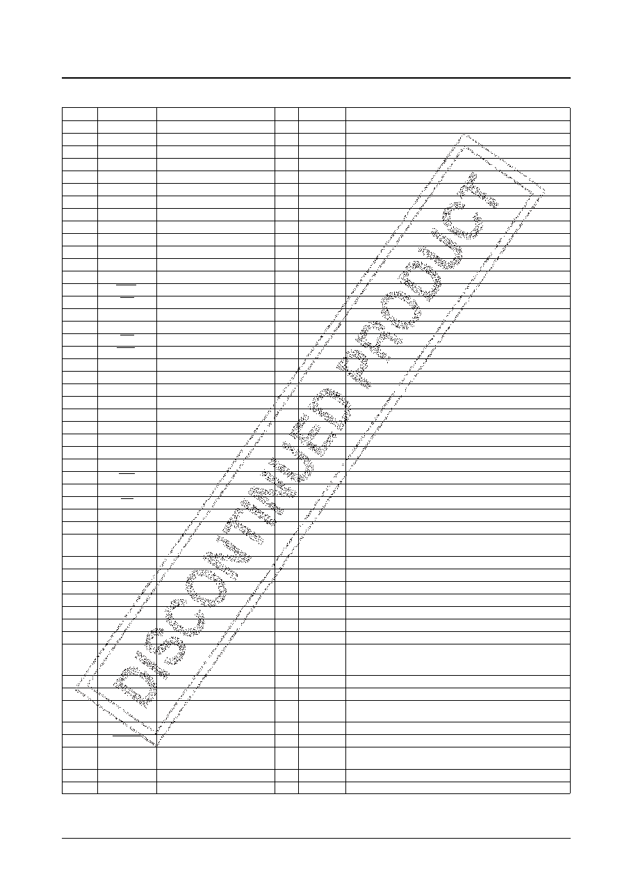
Pin no.
Pin
Pin type
I/O
Polarity
Pin function
1
TEST1
Test input
I
Positive
Test input. Must be connected to ground during normal operation.
2
TEST2
Test input
I
Positive
Test input. Must be connected to ground during normal operation.
3
TEST3
Test output
O
Positive
Test output
4
TEST4
Test input
I
Positive
Test input. Must be connected to ground during normal operation.
5
TEST5
Test input
I
Positive
Test input. Must be connected to ground during normal operation.
6
TEST6
Test input
I
Positive
Test input. Must be connected to ground during normal operation.
7DVDD1
Power supply (+5 V)
—
Digital system power supply
8CE
Enable input
I
Positive
Serial I/O data control input
9DO
Data output
O
Positive
Serial data output
10
DI
Data input
I
Positive
Serial data input
11
CL
Clock input
I
Positive
Serial data I/O clock input
12
PSC1
Monitor 1 output
O
Positive
Serial input monitor signal output
13
PSC2
Monitor 2 output
O
Positive
Command monitor signal output
14
WAIT
Wait signal output
O
Negative
Serial input wait signal output (for use with bit maps)
15
INT
Wait signal output
O
Negative
Serial input wait signal output (for use with the sprite function)
16
TEST7
Test input
I
Positive
Test input. Must be connected to ground during normal operation.
17
DVSS1
Ground
—
Digital system ground
18
WE
DRAM output
O
Negative
DRAM write enable signal output
19
RAS
DRAM output
O
Negative
DRAM row address strobe signal output
20
A0
DRAM output
I/O
Positive
DRAM address (A0) output (Functions as an input in test mode.)
21
A1
DRAM output
I/O
Positive
DRAM address (A1) output (Functions as an input in test mode.)
22
A2
DRAM output
I/O
Positive
DRAM address (A2) output (Functions as an input in test mode.)
23
A3
DRAM output
I/O
Positive
DRAM address (A3) output (Functions as an input in test mode.)
24
A4
DRAM output
I/O
Positive
DRAM address (A4) output (Functions as an input in test mode.)
25
A5
DRAM output
I/O
Positive
DRAM address (A5) output (Functions as an input in test mode.)
26
A6
DRAM output
I/O
Positive
DRAM address (A6) output (Functions as an input in test mode.)
27
A7
DRAM output
I/O
Positive
DRAM address (A7) output (Functions as an input in test mode.)
28
DB0
DRAM input and output
I/O
Positive
DRAM data (D0) input and output
29
CAS
DRAM output
O
Negative
DRAM column address strobe signal output
30
DB1
DRAM input and output
I/O
Positive
DRAM data (D1) input and output
31
OE
DRAM output
O
Negative
DRAM read enable signal output
32
DB2
DRAM input and output
I/O
Positive
DRAM data (D2) input and output
33
DB3
DRAM input and output
I/O
Positive
DRAM data (D3) input and output
34
CB
Color bar selection
I
Positive
Low: normal mode, high: color bar output
(A pull-down resistor is built in.)
35
TEST8
Test output
O
Positive
Test output
36
AVSS1
Ground
—
Analog system ground
37
AVDD1
Power supply (+5 V)
—
Analog system power supply
38
VIDEO1
Video signal (Y) output
O
—
Video (luminance) signal (analog) output (D/A converter output)
39
BIAS
Capacitor connection
O
—
Connections for a ripple exclusion capacitor
40
VIDEO2
Video signal (C) output
O
—
Video (chrominance) signal (analog) output (D/A converter output)
41
BFP
Burst flag signal output
O
Positive
Burst signal output timing flag output
Line count selection
42
LINE
Line count selection
I
—
NTSC mode - Low: 263H, high: 262H
PAL mode - Low: 314H, high: 312H
43
FSCIN
Clock input
I
Positive
Superimpose subcarrier clock input (A feedback resistor is built in.)
44
VSYNC
Vertical synchronization output
O
Negative
Vertical synchronizing signal output
45
TEST9
Test input
I
Positive
Test input. Must be connected to ground during normal operation.
(A pull-down resistor is built in.)
46
YS
Superimpose output
O
Negative
Superimpose control output
47
CSYNC
Composite synchronization output
O
Negative
Composite synchronizing signal output
48
4FSC2
Clock input
I
Positive
External clock input for the superimpose function
(A feedback resistor is built in.)
49
TEST10
Test output
O
Positive
Test output
50
TEST11
Test output
O
Positive
Test output
Continued on next page.
相關PDF資料 |
PDF描述 |
|---|---|
| LC7871E | SPECIALTY CONSUMER CIRCUIT, PQFP100 |
| LC7871NE | SPECIALTY CONSUMER CIRCUIT, PQFP100 |
| LC7872E | SPECIALTY CONSUMER CIRCUIT, PQFP64 |
| LC7874E | SPECIALTY CONSUMER CIRCUIT, PQFP64 |
| LC78835K | SPECIALTY CONSUMER CIRCUIT, PDIP24 |
相關代理商/技術參數 |
參數描述 |
|---|---|
| LC7871E | 制造商:SANYO 制造商全稱:Sanyo Semicon Device 功能描述:CD Graphics Decoder |
| LC7871NE | 制造商:SANYO 制造商全稱:Sanyo Semicon Device 功能描述:CD Graphics Decoder |
| LC7872E | 制造商:Panasonic Industrial Company 功能描述:IC |
| LC7874E | 制造商:SANYO 制造商全稱:Sanyo Semicon Device 功能描述:CD Graphics Decorder |
| LC7876E | 制造商:未知廠家 制造商全稱:未知廠家 功能描述: |
發布緊急采購,3分鐘左右您將得到回復。