- 您現在的位置:買賣IC網 > PDF目錄361039 > LMH6570MAX (NATIONAL SEMICONDUCTOR CORP) 2:1 High Speed Video Multiplexer PDF資料下載
參數資料
| 型號: | LMH6570MAX |
| 廠商: | NATIONAL SEMICONDUCTOR CORP |
| 元件分類: | 多路復用及模擬開關 |
| 英文描述: | 2:1 High Speed Video Multiplexer |
| 中文描述: | 4-CHANNEL, VIDEO MULTIPLEXER, PDSO8 |
| 封裝: | SOIC-8 |
| 文件頁數: | 4/14頁 |
| 文件大小: | 831K |
| 代理商: | LMH6570MAX |
±
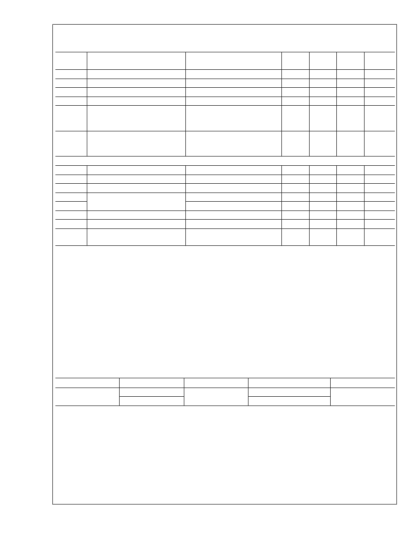
3.3V Electrical Characteristics
(Continued)
V
S
=
±
3.3V, R
L
= 100
, R
F
=576
, A
V
=2 V/V; Unless otherwise specified.
Symbol
Parameter
Conditions
(Note 2)
Min
(Note 5)
Typ
(Note 9)
1
-3
49
12.5
1.3
Max
(Note 5)
Units
VIO
IBN
PSRR
ICC
VIH
Input Offset Voltage
Input Bias Current (Note 7)
Power Supply Rejection Ratio
Supply Current
Logic High Threshold
V
IN
= 0V
V
IN
= 0V
DC, Input Referred
No Load
Select Pin & Shutdown pin (SEL,
SD),
VIH
)
V
+
* 0.4
Select Pin & Shutdown pin (SEL,
SD),
VIL
)
V
+
* 0.12
mV
μA
dB
mA
V
VIL
Logic Low Threshold
0.4
V
Miscellaneous Performance
RIN+
Input Resistance
CIN
Input Capacitance
ROUT
Output Resistance
VO
Output Voltage Range
VOL
CMIR
Input Voltage Range
IO
Linear Output Current (Note 3)
ISC
Short Circuit Current (Note 3)
5
k
pF
V
V
V
mA
mA
0.8
0.06
±
2
±
1.8
±
1.2
±
60
±
150
No Load
R
L
= 100
V
IN
= 0V
V
IN
=
±
1V, Output shorted to
ground
Note 1:
Absolute Maximum Ratings indicate limits beyond which damage to the device may occur. Operating Ratings indicate conditions for which the device is
intended to be functional, but specific performance is not guaranteed. For guaranteed specifications, see the Electrical Characteristics tables.
Note 2:
Electrical Table values apply only for factory testing conditions at the temperature indicated. Factory testing conditions result in very limited self-heating of
the device such that T
J
= T
A
. No guarantee of parametric performance is indicated in the electrical tables under conditions of internal self heating where T
J
>
T
A
.
See Applications Section for information on temperature de-rating of this device. Min/Max ratings are based on product testing, characterization and simulation.
Individual parameters are tested as noted.
Note 3:
The maximum output current (I
OUT
) is determined by the device power dissipation limitations (The junction temperature cannot be allowed to exceed
150C). See the Power Dissipation section of the Application Section for more details. A short circuit condition should be limited to 5 seconds or less.
Note 4:
Human Body model, 1.5k
in series with 100pF. Machine model, 0
In series with 200pF
Note 5:
Limits are 100% production tested at 25C. Limits over the operating temperature range are guaranteed through correlation using Statistical Quality Control
(SQC) methods.
Note 6:
Parameter guaranteed by design.
Note 7:
Positive Value is current into device.
Note 8:
Slew Rate is the average of the rising and falling edges.
Note 9:
Typical numbers are the most likely parametric norm.
Note 10:
Drift determined by dividing the change in parameter at temperature extremes by the total temperature change.
Ordering Information
Package
Part Number
LMH6570MA
LMH6570MAX
Package Marking
Transport Media
95 Units/Rail
2.5k Units Tape and Reel
NSC Drawing
8-Pin SOIC
LMH6570MA
M08A
L
www.national.com
4
相關PDF資料 |
PDF描述 |
|---|---|
| LMH6570 | 2:1 High Speed Video Multiplexer |
| LMH6574 | 4:1 High Speed Video Multiplexer |
| LMH6574MA | 4:1 High Speed Video Multiplexer |
| LMH6574MAX | 4:1 High Speed Video Multiplexer |
| LMH6622 | Dual Wideband, Low Noise, 160MHz, Operational Amplifiers |
相關代理商/技術參數 |
參數描述 |
|---|---|
| LMH6570MAX/NOPB | 功能描述:多路器開關 IC RoHS:否 制造商:Texas Instruments 通道數量:1 開關數量:4 開啟電阻(最大值):7 Ohms 開啟時間(最大值): 關閉時間(最大值): 傳播延遲時間:0.25 ns 工作電源電壓:2.3 V to 3.6 V 工作電源電流: 最大工作溫度:+ 85 C 安裝風格:SMD/SMT 封裝 / 箱體:UQFN-16 |
| LMH6572 | 制造商:NSC 制造商全稱:National Semiconductor 功能描述:Triple 2:1 High Speed Video Multiplexer |
| LMH6572_05 | 制造商:NSC 制造商全稱:National Semiconductor 功能描述:Triple 2:1 High Speed Video Multiplexer |
| LMH6572MQ | 功能描述:多路器開關 IC RoHS:否 制造商:Texas Instruments 通道數量:1 開關數量:4 開啟電阻(最大值):7 Ohms 開啟時間(最大值): 關閉時間(最大值): 傳播延遲時間:0.25 ns 工作電源電壓:2.3 V to 3.6 V 工作電源電流: 最大工作溫度:+ 85 C 安裝風格:SMD/SMT 封裝 / 箱體:UQFN-16 |
| LMH6572MQ/NOPB | 功能描述:多路器開關 IC RoHS:否 制造商:Texas Instruments 通道數量:1 開關數量:4 開啟電阻(最大值):7 Ohms 開啟時間(最大值): 關閉時間(最大值): 傳播延遲時間:0.25 ns 工作電源電壓:2.3 V to 3.6 V 工作電源電流: 最大工作溫度:+ 85 C 安裝風格:SMD/SMT 封裝 / 箱體:UQFN-16 |
發布緊急采購,3分鐘左右您將得到回復。