- 您現(xiàn)在的位置:買賣IC網(wǎng) > Datasheet目錄44 > MAX6664AEE+T (Maxim Integrated)IC TEMP MON FAN CNTRL 16-QSOP Datasheet資料下載
參數(shù)資料
| 型號(hào): | MAX6664AEE+T |
| 廠商: | Maxim Integrated |
| 文件頁(yè)數(shù): | 11/24頁(yè) |
| 文件大小: | 297K |
| 描述: | IC TEMP MON FAN CNTRL 16-QSOP |
| 產(chǎn)品培訓(xùn)模塊: | Lead (SnPb) Finish for COTS Obsolescence Mitigation Program |
| 標(biāo)準(zhǔn)包裝: | 2,500 |
| 功能: | 風(fēng)扇控制,溫度監(jiān)控器 |
| 傳感器類型: | 內(nèi)部和外部 |
| 感應(yīng)溫度: | -40°C ~ 125°C,外部傳感器 |
| 精確度: | ±2°C 本地(最大),±3°C 遠(yuǎn)程(最大) |
| 拓?fù)洌?/td> | ADC,多路復(fù)用器,寄存器庫(kù),測(cè)速計(jì) |
| 輸出類型: | I²C?/SMBus? |
| 輸出警報(bào): | 是 |
| 輸出風(fēng)扇: | 是 |
| 電源電壓: | 3 V ~ 5.5 V |
| 工作溫度: | -40°C ~ 125°C |
| 安裝類型: | 表面貼裝 |
| 封裝/外殼: | 16-SSOP(0.154",3.90mm 寬) |
| 供應(yīng)商設(shè)備封裝: | 16-QSOP |
| 包裝: | 帶卷 (TR) |
第1頁(yè)第2頁(yè)第3頁(yè)第4頁(yè)第5頁(yè)第6頁(yè)第7頁(yè)第8頁(yè)第9頁(yè)第10頁(yè)當(dāng)前第11頁(yè)第12頁(yè)第13頁(yè)第14頁(yè)第15頁(yè)第16頁(yè)第17頁(yè)第18頁(yè)第19頁(yè)第20頁(yè)第21頁(yè)第22頁(yè)第23頁(yè)第24頁(yè)
Temperature Monitors and
PWM Fan Controllers
______________________________________________________________________________________ 11
Automatic Fan-Control Mode
Automatic fan-speed control is selected by setting bits
[7:5] of configuration register 1 (00h) to 100 (to control
speed based on the remote temperature) or 101 (to
control speed based on both remote and local temper-
ature). Program a threshold, or starting temperature
TMIN, and the desired temperature range, T
RANGE
, into
the local temp T
MIN
/T
RANGE
register (24h) for local
temperature and into the remote temp T
MIN
/T
RANGE
register (25h) for remote temperature (Tables 10 and
11). If the fan control responds to both local and remote
temperatures, the higher PWM duty cycle has priority.
When the temperature exceeds T
MIN
, the fan is
enabled at a minimum duty cycle programmed in bits
[3:0] of the fan-speed configuration register (22h). The
duty cycle increases in proportion to the temperature
difference and reaches 100% at a temperature equal to
(T
MIN
+ T
RANGE
). A hysteresis of 5癈 is built into the
T
MIN
set point to prevent the fan from starting and stop-
ping when the temperature is at the set point.
Spin-Up
To ensure proper fan startup, the MAX6653/MAX6663/
MAX6664 can be set to drive the fan to 100% duty
cycle for a short period on startup, and then revert to
the correct duty cycle. The spin-up time is programmed
by bits [2:0] in the fan characteristics register (20h).
The spin-up feature can be disabled by setting bit 7 of
the fan-filter register (23h) to 1; POR value is zero.
Table 12 shows programming of the spin-up time.
Fan-Filter Mode
When the MAX6653/MAX6663/MAX6664 are used for
automatic fan-speed control, the fan-filter mode helps
minimize the audible effects of varying fan speeds. The
fan-filter mode limits the rate at which fan speed can
change. Each time a new temperature measurement is
made, the fan-filter mode allows the PWM duty cycle to
increment by a selectable amount. The duty cycle can
change by 1/240, 2/240, 4/240, or 8/240 (0.416%,
0.833%, 1.667%, or 3.333%) of the PWM period after
each temperature-monitoring cycle. This prevents sud-
den changes in fan speed, even when temperature
changes suddenly.
The filter mode is set by bit 0 of the fan-filter register
(23h). To enable the fan-filter mode, write a 1 to this bit.
Bits [6:5] of the same register control the size of the
PWM steps.
Note that the rate of change depends on both the value
selected by the fan-filter bits and on the temperature
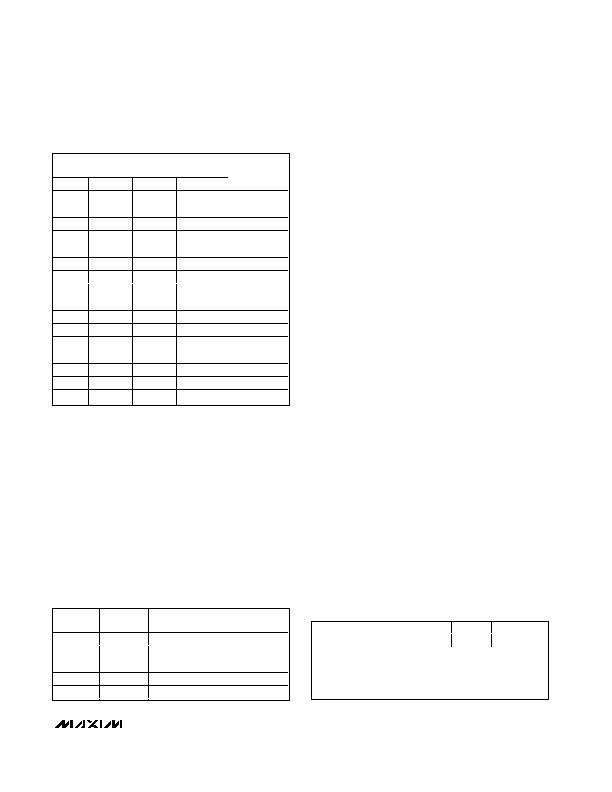
BITS [3:0] OF FAN-SPEED
CONFIGURATION REGISTER (22h)
BIT 3
BIT 2
BIT 1
BIT 0
% DUTY
CYCLE (%)
0
0
0
0
0
0
0
0
1
7
0
0
1
0
14
0
0
1
1
20
0
1
0
0
27
0
1
0
1
33
0
1
1
0
40
0
1
1
1
47
1
0
0
0
53
1
0
0
1
60
1
0
1
0
67
1
0
1
1
73
1
1
0
0
80
1
1
0
1
87
1
1
1
0
93
1
1
1
1
100
Table 9. Setting PWM Duty Cycle
Table 10. T
RANGE
Fan-Control Temperature
Range Bits [2:0] T
MIN
/T
RANGE
Registers
(24h and 25h)POR = 001
BIT 2
BIT 1
BIT 0
TEMPERATURE
RANGE (?/SPAN>C)
0
0
0
5
0
0
1
10
0
1
0
20
0
1
1
40
1
0
0
80
Table 11.T
MIN
Fan-Control Start
Temperature; Bits [7:3] T
MIN
/T
RANGE
Registers (24hPOR = 01000 and
25hPOR = 01100
BIT 7
BIT 6
BIT5
BIT 4
BIT3
MSB = +64癈
LSB = +4癈
Min threshold = 0癈
Max threshold = +127癈
LSB/step size = +4癈
POR = +48癈 or 01100b
相關(guān)PDF資料 |
PDF描述 |
|---|---|
| MAX6665ASA45+ | IC FAN CNTRL/DRVR 8-SOIC |
| MAX6670AUB45+ | IC TEMP SENSOR REMOTE 10-UMAX |
| MAX6678AEP92+ | IC TEMP MONITOR 2CH PWM 20-QSOP |
| MAX6681MEE+ | IC TEMP SENSOR SMBUS 16-QSOP |
| MAX6689UP34+ | IC 7CH PREC TEMP MONITOR 20TSSOP |
相關(guān)代理商/技術(shù)參數(shù) |
參數(shù)描述 |
|---|---|
| MAX6664AEE-TG075 | 制造商:Rochester Electronics LLC 功能描述: 制造商:Maxim Integrated Products 功能描述: |
| MAX6665ASA070 | 制造商:Maxim Integrated Products 功能描述: |
| MAX6665ASA40 | 功能描述:馬達(dá)/運(yùn)動(dòng)/點(diǎn)火控制器和驅(qū)動(dòng)器 RoHS:否 制造商:STMicroelectronics 產(chǎn)品:Stepper Motor Controllers / Drivers 類型:2 Phase Stepper Motor Driver 工作電源電壓:8 V to 45 V 電源電流:0.5 mA 工作溫度:- 25 C to + 125 C 安裝風(fēng)格:SMD/SMT 封裝 / 箱體:HTSSOP-28 封裝:Tube |
| MAX6665ASA40+ | 功能描述:馬達(dá)/運(yùn)動(dòng)/點(diǎn)火控制器和驅(qū)動(dòng)器 Fan Controller Driver RoHS:否 制造商:STMicroelectronics 產(chǎn)品:Stepper Motor Controllers / Drivers 類型:2 Phase Stepper Motor Driver 工作電源電壓:8 V to 45 V 電源電流:0.5 mA 工作溫度:- 25 C to + 125 C 安裝風(fēng)格:SMD/SMT 封裝 / 箱體:HTSSOP-28 封裝:Tube |
| MAX6665ASA40+T | 功能描述:馬達(dá)/運(yùn)動(dòng)/點(diǎn)火控制器和驅(qū)動(dòng)器 Fan Controller Driver RoHS:否 制造商:STMicroelectronics 產(chǎn)品:Stepper Motor Controllers / Drivers 類型:2 Phase Stepper Motor Driver 工作電源電壓:8 V to 45 V 電源電流:0.5 mA 工作溫度:- 25 C to + 125 C 安裝風(fēng)格:SMD/SMT 封裝 / 箱體:HTSSOP-28 封裝:Tube |
發(fā)布緊急采購(gòu),3分鐘左右您將得到回復(fù)。