- 您現在的位置:買賣IC網 > PDF目錄385637 > MSAGA11F120D (MICROSEMI CORP-COLORADO) Fast IGBT Die for Implantable Cardio Defibrillator Applications PDF資料下載
參數資料
| 型號: | MSAGA11F120D |
| 廠商: | MICROSEMI CORP-COLORADO |
| 元件分類: | 功率晶體管 |
| 英文描述: | Fast IGBT Die for Implantable Cardio Defibrillator Applications |
| 中文描述: | 22 A, 1200 V, N-CHANNEL IGBT |
| 封裝: | DIE-2 |
| 文件頁數: | 1/3頁 |
| 文件大小: | 221K |
| 代理商: | MSAGA11F120D |
MSC0947.PDF 2/5/99
All Ratings: Device Packaged in TO-3 or Microsemi CoolPack Package, T
C
= 25
°
C unless otherwise specified
DESCRIPTION:
N-Channel enhancement mode high density IGBT die
Passivation: Polyimide, 20 um, over Silicon Nitride, .8um
Emitter Metallization: Al/1%Si for aluminum wire bonding, 3.2 um typical.
Collector/Gate Metallization: Ti – Ni (1 um) – Ag (0.2 um) for soft solder attach
FEATURES:
Low Forward Voltage Drop, Low Tail Current
Avalanche and Surge Rated
High Freq. Switching to 20KHz
Ultra Low Leakage Current
RBSOA and SCSOA Rated
Available with Lot Acceptance Testing Spec MSAGA11F120DL, "-L" Suffix
MAXIMUM RATINGS:
STATIC ELECTRICAL CHARACTERISTICS:
2830 S. Fairview Street
Santa Ana, CA 92704
Phone: (714) 979-8220
Fax: (714) 559-5989
SYMBOL
PARAMETER
VALUE
UNIT
V
CES
V
CGR
V
EG
V
GE
I
C1
I
C2
I
CM
I
CM1
I
CM2
I
Csurge2
Collector-Emitter Voltage
Collector-Gate Voltage (R
GE
= 20K
W
)
Emitter-Collector Voltage
Gate-Emitter Voltage
Continuous Collector Current @ T
C
= 25
°
C
Continuous Collector Current @ T
C
= 110
°
C
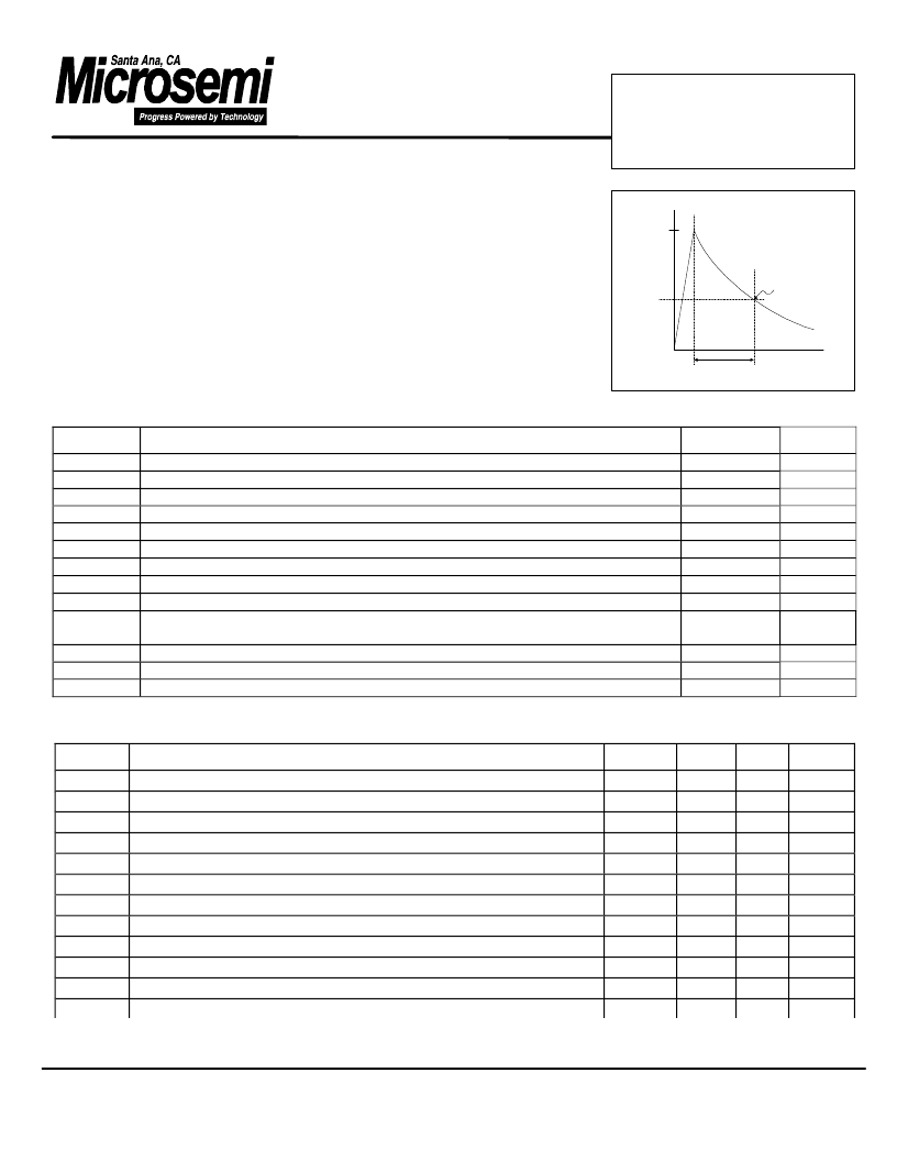
Surge Current (10
m
s x 4ms double exponential, see figure 2)
Pulsed Collector Current
x
@ T
C
= 25
°
C
Pulsed Collector Current
x
@ T
C
= 110
°
C
Surge Current: tp= 2 us (ton= 1.5
m
s; toff= 0.5
m
s to 50% decay), 10 pulses, duty
cycle= 1:2,500,000 (12 pulses/minute)
Single Pulse Avalanche Energy
y
Total Power Dissipation
Operating and Storage: Junction Temperature Range
1200
1200
15
±20
22
11
55
44
22
400
Volts
Volts
Volts
Volts
Amps
Amps
Amps
Amps
Amps
Apk
E
AS
P
D
T
J,
T
STG
10
125
mJ
Watts
°
C
-55 to 150
MSAGA11F120D
Fast IGBT Die for Implantable
Cardio Defibrillator
Applications
S
C
)
1
μ
s
55
10
μ
s
4000
μ
s
Time -
μ
sec
35-50% of
I
CM
Max
SYMBOL
CHARACTERISTIC / TEST CONDITIONS
MIN
TYP
MAX
UNIT
BV
CES
RBV
CES
Collector-Emitter Breakdown Voltage (V
GE
= 0V, I
C
= 0.5mA)
Collector-Emitter Reverse Breakdown Voltage
z
(V
GE
= 20V, I
C
= 10mA)
Gate Threshold Voltage (V
CE
=
V
GE
,
I
C
=
350
m
A, T
J
= 37
°
C
Gate Threshold Voltage (V
CE
=
V
GE
,
I
C
=
350
m
A, T
J
= 25
°
C
Collector-Emitter On Voltage (V
GE
=
15V, I
C
=
I
C2,
T
J
=
25
°
C)
Collector-Emitter On Voltage (V
GE
=
15V, I
C
=
I
C2,
T
J
= 37
°
C)
Collector-Emitter On Voltage (V
GE
=
15V, I
C
=
I
C2,
T
J
= 1
25
°
C)
Collector Cut-off Current (V
CE
= 80%V
CES
,
V
GE
= 0V,
T
J
=
25
°
C)
Collector Cut-off Current (V
CE
= 80%V
CES
,
V
GE
= 0V,
T
J
= 37
°
C)
Collector Cut-off Current (V
CE
= 80%V
CES
,
V
GE
= 0V,
T
J
= 1
25
°
C)
Gate-Emitter Leakage Current (V
GE
= ±25V,
V
CE
=0V)
Gate-Emitter Leakage Current (V
GE
= ±25V,
V
CE
=0V), Tj= 37
°
C
1200
-15
Volts
Volts
Volts
Volts
Volts
Volts
Volts
uA
uA
uA
nA
nA
5.7
5.5
3.1
3.5
4
0.02
0.07
V
GE
(TH)
V
CE
(ON)
4.5
6.5
3.5
4.5
10
I
CES
1000
±100
2
4
I
GES
相關PDF資料 |
PDF描述 |
|---|---|
| MSAGZ52F120A | Circular Connector; No. of Contacts:37; Series:MS27468; Body Material:Aluminum; Connecting Termination:Crimp; Connector Shell Size:15; Circular Contact Gender:Socket; Circular Shell Style:Jam Nut Receptacle; Insert Arrangement:15-35 RoHS Compliant: No |
| MSAHX60F60A | N-CHANNEL INSULATED GATE BIPOLAR TRANSISTOR |
| MSAGX60F60A | N-CHANNEL INSULATED GATE BIPOLAR TRANSISTOR |
| MSAHX75L60C | N-CHANNEL INSULATED GATE BIPOLAR TRANSISTOR |
| MSARS200S10L | HIGH CURRENT CAPABILITY LOW VOLTAGE DROP STANDARD RECOVERY RECTIFIER |
相關代理商/技術參數 |
參數描述 |
|---|---|
| MSA-G-W | 制造商:Adam Technologies Inc 功能描述: |
| MSAGX60F60A | 制造商:Microsemi Corporation 功能描述:TRANS IGBT CHIP N-CH 600V 60A 3PIN COOLPACK1 - Bulk |
| MSAGX75F60A | 制造商:Microsemi Corporation 功能描述:TRANS IGBT CHIP N-CH 600V 75A 3PIN COOLPACK1 - Bulk |
| MSAGX75L60A | 制造商:Microsemi Corporation 功能描述:TRANS IGBT CHIP N-CH 600V 75A 3PIN COOLPACK1 - Bulk |
| MSAGZ52F120A | 制造商:Microsemi Corporation 功能描述:TRANS IGBT CHIP N-CH 1.2KV 52A 3PIN COOLPACK1 - Bulk |
發布緊急采購,3分鐘左右您將得到回復。