- 您現在的位置:買賣IC網 > PDF目錄382378 > PCA9515 (NXP Semiconductors N.V.) I2C-bus repeater PDF資料下載
參數資料
| 型號: | PCA9515 |
| 廠商: | NXP Semiconductors N.V. |
| 英文描述: | I2C-bus repeater |
| 中文描述: | I2C總線中繼器 |
| 文件頁數: | 3/11頁 |
| 文件大小: | 128K |
| 代理商: | PCA9515 |
Philips Semiconductors
Product data sheet
PCA9515
I
2
C-bus repeater
2004 Jun 24
3
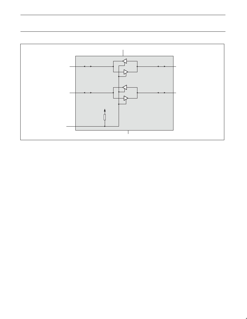
PCA9515
V
CC
SDA1
SCL1
SCL0
SDA0
SU01323
PULL-UP
RESISTOR
EN
GND
Figure 2. PCA9515 block diagram
The output pull-down of each internal buffer is set for approximately
0.5 V, while the input threshold of each internal buffer is set about
0.07 V lower, when the output is internally driven LOW. This
prevents a lock-up condition from occurring.
FUNCTIONAL DESCRIPTION
The PCA9515 BiCMOS integrated circuit contains two identical
buffer circuits which enable I
2
C and similar bus systems to be
extended without degradation of system performance.
The PCA9515 BiCMOS integrated circuit contains two bi-directional,
open drain buffers specifically designed to support the standard
low-level-contention arbitration of the I
2
C-bus. Except during
arbitration or clock stretching, the PCA9515 acts like a pair of
non-inverting, open drain buffers, one for SDA and one for SCL.
Enable
The EN pin is active high with an internal pull up and allows the user
to select when the repeater is active. This can be used to isolate a
badly behaved slave on power up until after the system power up
reset. It should never change state during an I
2
C operation because
disabling during a bus operation will hang the bus and enabling part
way through a bus cycle could confuse the I
2
C parts being enabled.
The enable pin should only change state when the global bus and
the repeater port are in an idle state to prevent system failures.
I
2
C Systems
As with the standard I
2
C system, pull-up resistors are required to
provide the logic HIGH levels on the Buffered bus. (Standard
open-collector configuration of the I
2
C-bus). The size of these
pull-up resistors depends on the system, but each side of the
repeater must have a pull-up resistor. This part designed to work
with standard mode and fast mode I
2
C devices in addition to SMBus
devices. Standard mode I
2
C devices only specify 3 mA output drive,
this limits the termination current to 3 mA in a generic I
2
C system
where standard mode devices and multiple masters are possible.
Under certain conditions higher termination currents can be used.
Please see Application Note AN255 “I
2
C & SMBus Repeaters, Hubs
and Expanders”for additional information on sizing resistors and
precautions when using more than one PCA9515/PCA9516 in a
system or using the PCA9515/16 in conjunction with the P82B96.
相關PDF資料 |
PDF描述 |
|---|---|
| PCA9516PW | 5-channel I2C hub |
| PCA9516 | 5-channel I2C hub |
| PCA9516D | 5-channel I2C hub |
| PCA9517 | Level translating I2C-bus repeater |
| PCA9517D | H 1/14D RED BD |
相關代理商/技術參數 |
參數描述 |
|---|---|
| PCA9515A | 制造商:PHILIPS 制造商全稱:NXP Semiconductors 功能描述:I2C-bus repeater |
| PCA9515AD | 功能描述:接口-信號緩沖器、中繼器 Dual Bidir I2C Bus & SMBus Repeater RoHS:否 制造商:Texas Instruments 工作電源電壓: 工作溫度范圍: 安裝風格:SMD/SMT 封裝 / 箱體:VSSOP-8 封裝:Reel |
| PCA9515AD,112 | 功能描述:接口-信號緩沖器、中繼器 I2C BUS REPEATER RoHS:否 制造商:Texas Instruments 工作電源電壓: 工作溫度范圍: 安裝風格:SMD/SMT 封裝 / 箱體:VSSOP-8 封裝:Reel |
| PCA9515AD,118 | 功能描述:接口-信號緩沖器、中繼器 I2C BUS REPEATER RoHS:否 制造商:Texas Instruments 工作電源電壓: 工作溫度范圍: 安裝風格:SMD/SMT 封裝 / 箱體:VSSOP-8 封裝:Reel |
| PCA9515AD,118-CUT TAPE | 制造商:NXP 功能描述:PCA9515A Series 3.6 V 2-Channel Bidirectional Buffer I2C-bus repeater - SOIC - 8 |
發布緊急采購,3分鐘左右您將得到回復。