- 您現(xiàn)在的位置:買賣IC網(wǎng) > PDF目錄376314 > romr0002 (SIEMENS AG) MultiMediaCard R0002 2 Mbyte ROM(多媒體卡 R0002 2 Mbyte ROM) PDF資料下載
參數(shù)資料
| 型號: | romr0002 |
| 廠商: | SIEMENS AG |
| 英文描述: | MultiMediaCard R0002 2 Mbyte ROM(多媒體卡 R0002 2 Mbyte ROM) |
| 中文描述: | 多媒體R0002 2字節(jié)的光盤(多媒體卡R0002 2字節(jié)光盤) |
| 文件頁數(shù): | 18/41頁 |
| 文件大小: | 207K |
| 代理商: | ROMR0002 |
第1頁第2頁第3頁第4頁第5頁第6頁第7頁第8頁第9頁第10頁第11頁第12頁第13頁第14頁第15頁第16頁第17頁當(dāng)前第18頁第19頁第20頁第21頁第22頁第23頁第24頁第25頁第26頁第27頁第28頁第29頁第30頁第31頁第32頁第33頁第34頁第35頁第36頁第37頁第38頁第39頁第40頁第41頁
Siemens
Product Manual R0002
Semiconductor Group
18
3.1
6.2
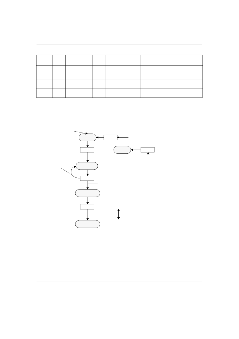
Card identification mode
All the data communication in the card identification mode uses only the command line (CMD).
Power on
Figure 4: MultiMediaCard state diagram (card identification mode)
The host starts the card identification process in open drain mode with the identification clock rate
f
OD
(generated by a push pull driver stage). The open drain driver stages on the CMD line allow the
parallel card operation during card identification.
After the bus is activated the host will request the cards to send their valid operation conditions with
the command
SEND_OP_COND
(CMD1). Since the bus is in open drain mode, as long as there is
more than one card with operating conditions restrictions, the host gets in the response to the
CMD1 a “wired or” operation condition restrictions of those cards. The host then must pick a com-
1
The default block length is as specified in the CSD.
2
The data transferred must not cross a physical block boundary unless RD_BLK_MISALIGN is set in the CSD.
CMD
INDEX
type
argument
resp
abbreviation
command description
CMD16
ac
[31:0] block
length
R1
SET_BLOCKLEN
Selects a block length (in bytes) for all
following block commands (read and
write).
1
Reads a block of the size selected by
the SET_BLOCKLEN command.
2
Continuously send blocks of data until
interrupted by a stop command.
CMD17
adtc
[31:0] data
address
[31:0] data
address
R1
READ_SINGLE_
BLOCK
READ_MULTIPLE_
BLOCK
CMD18
adtc
R1
Table 17: Block oriented read commands (class 2)
Ready State
(ready)
CMD1
Inactive
State (ina)
Idle State
(idle)
Identification
State (ident)
CMD0
CMD3
CMD2
from all states except (ina)
from all states in
data-transfer-mode
CMD15
card looses bus
card wins bus
data-transfer mode
card-identification mode
Stand-by State
(stby)
相關(guān)PDF資料 |
PDF描述 |
|---|---|
| romr0008 | MultiMediaCard R0008 8 Mbyte ROM(多媒體卡 R0002 8 Mbyte ROM) |
| ROS-1000PV | Surface Mount Voltage Controlled Oscillator |
| ROS-1700W | Voltage Controlled Oscillator |
| rosa51 | MultiMediaCard Adapter(多媒體卡適配器) |
| ROSE-1 | FREQUENCY MIXERS |
相關(guān)代理商/技術(shù)參數(shù) |
參數(shù)描述 |
|---|---|
| RONDOREX W22 | 制造商:REX 功能描述:TIME SWITCH 7DAY 2CHANNEL |
| ROPE KIT 15 | 制造商:IMO Precision Controls Ltd 功能描述:ROPE KIT 15M |
| ROPE KIT 15 | 制造商:IMO Precision Controls Ltd 功能描述:ROPE KIT 15M |
| ROPE KIT 30 | 制造商:IMO Precision Controls Ltd 功能描述:ROPE KIT 30M |
| ROPE KIT 30 | 制造商:IMO Precision Controls Ltd 功能描述:ROPE KIT 30M |
發(fā)布緊急采購,3分鐘左右您將得到回復(fù)。