- 您現在的位置:買賣IC網 > Datasheet目錄46 > SG6932SZ (Fairchild Semiconductor)IC PFC CONTROLLER CCM 16SOP Datasheet資料下載
參數資料
| 型號: | SG6932SZ |
| 廠商: | Fairchild Semiconductor |
| 文件頁數: | 15/20頁 |
| 文件大小: | 919K |
| 描述: | IC PFC CONTROLLER CCM 16SOP |
| 標準包裝: | 2,500 |
| 模式: | 連續導電(CCM) |
| 頻率 - 開關: | 65kHz |
| 電流 - 啟動: | 10µA |
| 電源電壓: | 14 V ~ 20 V |
| 工作溫度: | -40°C ~ 85°C |
| 安裝類型: | 表面貼裝 |
| 封裝/外殼: | 16-SOIC(0.154",3.90mm 寬) |
| 供應商設備封裝: | 16-SOIC |
| 包裝: | 帶卷 (TR) |
?2007 Fairchild Semiconductor Corporation
www.fairchildsemi.com
SG6932 " Rev. 1.1.3
15
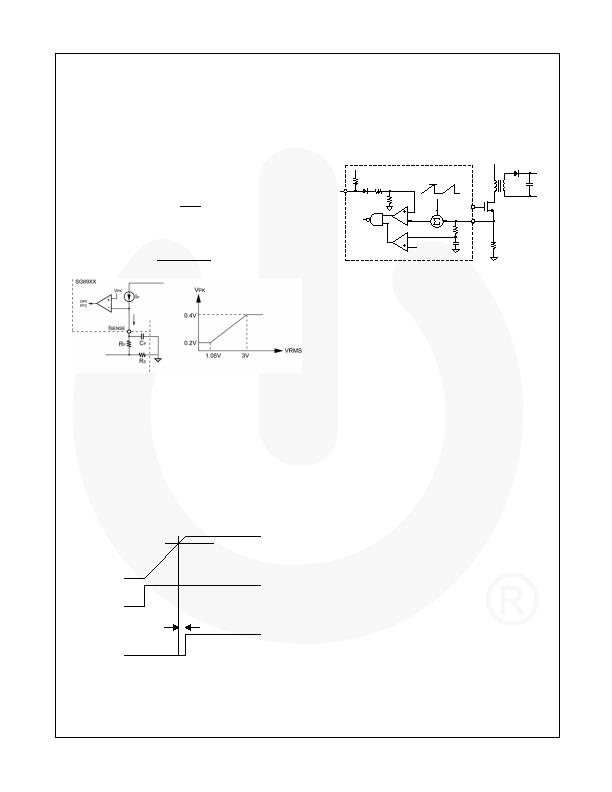
Cycle-by-Cycle Current Limiting
SG6932 provides cycle-by-cycle current limiting for
both PFC and PWM stages. Figure 29 shows the peak
current limit for the PFC stage. The PFC gate drive is
terminated once the voltage on the ISENSE pin goes
below V
PK
.
The V
RMS
voltage determines the V
PK
voltage. The
relationship between V
PK
and V
RMS
is shown in Figure 29.
The amplitude of the constant current, I
P,
is determined
by the internal current reference, I
T
, according to the
following equation:
I
T
P
R
)
(
2
.
1
2
I
2
I
V
?/DIV>
=
?/DIV>
=
(7)
Therefore, the peak current of the I
S
is given by
(V
RMS
<1.05V):
S
P
P
peak
_
S
R
2
.
0
)
R
I
(
I
(V)
?/DIV>
=
(8)
Figure 29. Current Limit
Power-On Sequence and Soft-Start
The SG6932 is enabled whenever the line voltage is
higher than the brownout threshold. Once the SG6932
is active, the PFC stage is enabled first. The PWM
stage is enabled following a 4ms delay time after
FBPFC voltage exceeds 2.7V. During start-up of PWM
stage, the SS pin charges an external capacitor with a
constant current source. The voltage on FBPWM is
clamped by SS during start-up. In the event of a
protection condition occurring and/or PWM being
disabled, the SS pin is quickly discharged.
2.7V
3V
OPFC
FBPFC
OPWM
4ms
Figure 30. Power-On Sequence
Forward PWM and Slope Compensation
The PWM stage is designed for forward power
converters. Peak-current-mode control is used to
optimize system performance. Slope compensation is
added to stabilize the current loop. The SG6932 inserts
a synchronized, positively sloped ramp at each
switching cycle. The positively sloped ramp is
represented by the voltage signal V
s-comp
. In this
example, the voltage of the ramp signal is 0.55V.
FBPWM
SG69XX
0.55V
0.7V
+
+
IPWM
Figure 31. Slope Compensation
Limited Power Control
Every time the output of power supply is shorted or
overloaded, the FBPWM voltage increases. If the FB
voltage is higher than a designed threshold of 4.2V for
longer than 95ms, the PWM output is turned off.
Gate Drivers
SG6932 output stages are fast totem-pole gate drivers.
The output driver is clamped by an internal 18V Zener
diode to protect the power MOSFET.
Protections
The SG6932 provides full protection functions to
prevent the power supply and the load from being
damaged. The protection features include:
PFC Feedback Over-Voltage Protection. When the
PFC feedback voltage exceeds the over-voltage
threshold, SG6932 inhibits the PFC switching signal.
This protection prevents the PFC power converter from
operating abnormally while the FBPFC pin is open.
Second PFC Over-Voltage Protection (OVP_PFC). The
PFC stage over-voltage input. The comparator disables
the PFC output driver if this input exceeds 3.25V. This
pin can be connected to the FBPFC pin or the PFC
boost output through a divider network. This pin
provides an extra input for PFC over-voltage protection.
PFC Feedback Under-Voltage Protection. The SG6932
stops the PFC switching signal whenever the PFC
feedback voltage drops below the under-voltage
threshold. This protection feature prevents the PFC
power converter from experiencing abnormal conditions
while the FBPFC pin is shorted to ground.
V
DD
Over-Voltage Protection. The PFC and PWM
stages are disabled whenever the V
DD
voltage exceeds
the over-voltage threshold.
RI Pin Open / Short Protection. The RI pin is used to
set the switching frequency and internal current
reference. The PFC and PWM stages of SG6932 are
disabled whenever the RI pin is short or open.
相關PDF資料 |
PDF描述 |
|---|---|
| SG6961SY | IC PFC CTRLR AVERAGE CURR 8SOIC |
| SI3500-A-GM | IC POE SWITCH PWR OVER LAN 20QFN |
| SI786LSG-E3 | IC REG QD BUCK/LINEAR 28SSOP |
| SIC417CD-T1-E3 | IC REG DL BCK/LINEAR SYNC 32MLPQ |
| SP619EK-L/TR | IC HIGH CURRENT SW SOT23-6 |
相關代理商/技術參數 |
參數描述 |
|---|---|
| SG6961 | 制造商:FAIRCHILD 制造商全稱:Fairchild Semiconductor 功能描述:Power Factor Controller |
| SG6961BSTA_DBB14 WAF | 制造商:Fairchild Semiconductor Corporation 功能描述: |
| SG6961DZ | 功能描述:功率因數校正 IC Grn Mode PFC/Forward PWM Controller RoHS:否 制造商:Fairchild Semiconductor 開關頻率:300 KHz 最大功率耗散: 最大工作溫度:+ 125 C 安裝風格:SMD/SMT 封裝 / 箱體:SOIC-8 封裝:Reel |
| SG6961SY | 功能描述:功率因數校正 IC Power Factor Controller RoHS:否 制造商:Fairchild Semiconductor 開關頻率:300 KHz 最大功率耗散: 最大工作溫度:+ 125 C 安裝風格:SMD/SMT 封裝 / 箱體:SOIC-8 封裝:Reel |
| SG6961SZ | 功能描述:功率因數校正 IC Power Factor Controller RoHS:否 制造商:Fairchild Semiconductor 開關頻率:300 KHz 最大功率耗散: 最大工作溫度:+ 125 C 安裝風格:SMD/SMT 封裝 / 箱體:SOIC-8 封裝:Reel |
發布緊急采購,3分鐘左右您將得到回復。