- 您現在的位置:買賣IC網 > PDF目錄98215 > TFP401APZPG4 (TEXAS INSTRUMENTS INC) SPECIALTY CONSUMER CIRCUIT, PQFP100 PDF資料下載
參數資料
| 型號: | TFP401APZPG4 |
| 廠商: | TEXAS INSTRUMENTS INC |
| 元件分類: | 消費家電 |
| 英文描述: | SPECIALTY CONSUMER CIRCUIT, PQFP100 |
| 封裝: | 14 X 14 MM, 1 MM HEIGHT, 0.50 MM PITCH, GREEN, PLASTIC, HTQFP-100 |
| 文件頁數: | 6/20頁 |
| 文件大小: | 295K |
| 代理商: | TFP401APZPG4 |
TFP401, TFP401A
TI
PanelBus DIGITAL RECEIVER
SLDS120C - MARCH 2000 REVISED MAY 2011
14
POST OFFICE BOX 655303
DALLAS, TEXAS 75265
TFP401A incorporates HSYNC jitter immunity (continued)
This HSYNC regeneration circuit is transparent to the monitor and need not be removed even if the transmitted
HSYNC is stable. For example, the PanelBus line of DVI 1.0 compliant transmitters, such as the TFP6422 and
TFP420, do not have the HSYNC jitter problem. The TFP401A will operate correctly with either compliant or
noncompliant transmitters. In contrast, the TFP401 is ideal for customers who have control over the transmit
portion of the design such as bundled system manufacturers and for internal monitor use (the DVI connection
between monitor and panel modules).
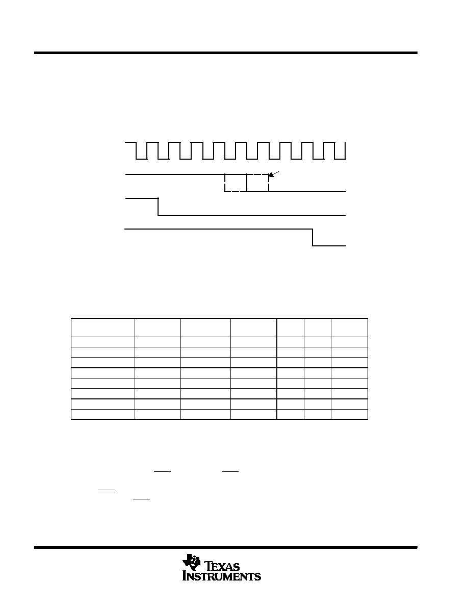
HSYNC Shift by ± 1 Clock
ODCK
HSYNC IN
DE
HSYNC OUT
Figure 16. HSYNC Regeneration Timing Diagram
TFP401/401A modes of operation
The TFP401/401A provides systems design flexibility and value by providing the system designer with
configurable options or modes of operation to support varying system architectures. The following table outlines
the various panel modes that can be supported along with appropriate external control pin settings.
PANEL
PIXEL RATE
ODCK LATCH
EDGE
ODCK
DFO
PIXS
OCK_INV
TFT or 16-bit DSTN
1 pix/clock
Falling
Free run
0
TFT or 16-bit DSTN
1 pix/clock
Rising
Free run
0
1
TFT
2 pix/clock
Falling
Free run
0
1
0
TFT
2 pix/clock
Rising
Free run
0
1
24-bit DSTN
1 pix/clock
Falling
Gated low
1
0
NONE
1 pix/clock
Rising
Gated low
1
0
1
24-bit DSTN
2 pix/clock
Falling
Gated low
1
0
24-bit DSTN
2 pix/clock
Rising
Gated low
1
TFP401/401A output driver configurations
The TFP401/401A provides flexibility by offering various output driver features that can be used to optimize
power consumption, ground-bounce and power-supply noise. The following sections outline the output driver
features and their effects.
Output driver power down (PDO = low), Pulling PDO low will place all the output drivers, except CTL1 and
SCDT, into a high-impedance state. The SCDT output which indicates link-disabled or link-inactive can be tied
directly to the PDO input to disable the output drivers when the link is inactive or when the cable is disconnected.
An internal pullup on the PDO pin will default the TFP401/401A to the normal nonpower down output drive mode
if left unconnected.
相關PDF資料 |
PDF描述 |
|---|---|
| TFP401PZP | SPECIALTY CONSUMER CIRCUIT, PQFP100 |
| TFP401PZPG4 | SPECIALTY CONSUMER CIRCUIT, PQFP100 |
| TFP403PZP | SPECIALTY CONSUMER CIRCUIT, PQFP100 |
| TFP403PZPG4 | SPECIALTY CONSUMER CIRCUIT, PQFP100 |
| TFP420PAP | SPECIALTY CONSUMER CIRCUIT, PQFP64 |
相關代理商/技術參數 |
參數描述 |
|---|---|
| TFP401PZP | 功能描述:顯示接口集成電路 PanelBus DVI Receiver 165MHz RoHS:否 制造商:Texas Instruments 電源電流:125 mA 工作溫度范圍:- 40 C to + 105 C 封裝 / 箱體:WQFN-60 封裝:Reel |
| TFP401PZPG4 | 功能描述:顯示接口集成電路 PanelBus DVI Rcvr RoHS:否 制造商:Texas Instruments 電源電流:125 mA 工作溫度范圍:- 40 C to + 105 C 封裝 / 箱體:WQFN-60 封裝:Reel |
| TFP403 | 制造商:TI 制造商全稱:Texas Instruments 功能描述:TI PANEBUS DIGITAL RECEIVER |
| TFP403PZP | 功能描述:顯示接口集成電路 PanelBus DVI Receiver RoHS:否 制造商:Texas Instruments 電源電流:125 mA 工作溫度范圍:- 40 C to + 105 C 封裝 / 箱體:WQFN-60 封裝:Reel |
| TFP403PZPG4 | 功能描述:顯示接口集成電路 PanelBus DVI Rcvr RoHS:否 制造商:Texas Instruments 電源電流:125 mA 工作溫度范圍:- 40 C to + 105 C 封裝 / 箱體:WQFN-60 封裝:Reel |
發布緊急采購,3分鐘左右您將得到回復。