- 您現在的位置:買賣IC網 > PDF目錄98246 > TLC876CPWLE (TEXAS INSTRUMENTS INC) 1-CH 10-BIT PROPRIETARY METHOD ADC, PARALLEL ACCESS, PDSO28 PDF資料下載
參數資料
| 型號: | TLC876CPWLE |
| 廠商: | TEXAS INSTRUMENTS INC |
| 元件分類: | ADC |
| 英文描述: | 1-CH 10-BIT PROPRIETARY METHOD ADC, PARALLEL ACCESS, PDSO28 |
| 封裝: | TSSOP-28 |
| 文件頁數: | 14/23頁 |
| 文件大小: | 305K |
| 代理商: | TLC876CPWLE |
TLC876M, TLC876I, TLC876C
10-BIT 20 MSPS PARALLEL OUTPUT CMOS
ANALOG-TO-DIGITAL CONVERTERS
SLAS140C – JULY 1997 – REVISED MAY 1999
21
POST OFFICE BOX 655303
DALLAS, TEXAS 75265
PRINCIPLES OF OPERATION
digital inputs and outputs
Each of the digital control inputs, OE and STBY, has an input buffer powered from the DRVDD supply terminal.
With DRVDD set to 5 V, all digital inputs readily interface with 5 V CMOS logic. Using lower voltage CMOS logic,
DRVDD can be set to 3.3 V, lowering the nominal input threshold of all digital inputs to (3.3 V)/2 = 1.65 V, typically.
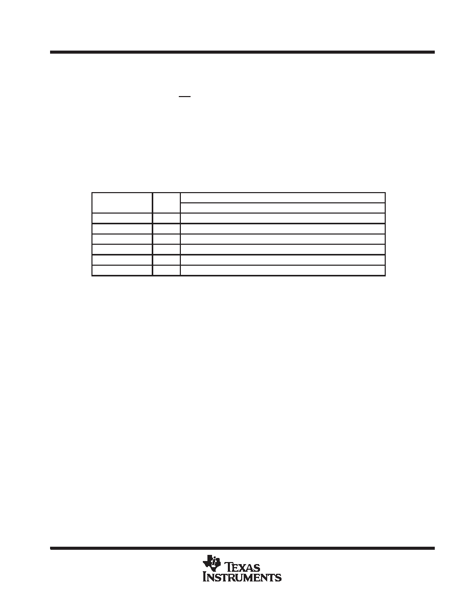
The digital output format is straight binary. For example, Table 1 shows the output format for voltage levels of
V(REFTS) = 4 V and V(REFBS) = 2 V.
A low power mode feature is provided such that when STBY is high and the clock is disabled, the static power
of the TLC876 drops significantly (see electrical characteristics table).
Table 1. Output Data Format
AIN VOLTAGE
THREE
DATA
(APPROXIMATE)
STATE
D9
D8
D7
D6
D5
D4
D3
D2
D1
D0
> 4 V
0
1
4 V
0
1
3 V
0
1
0
2 V
0
< 2 V
0
X
1
Z
grounding and layout rules
Proper grounding and layout techniques are essential for achieving optimal performance. The analog and digital
grounds on the TLC876 have been separated to optimize the management of return currents in a system. A
printed circuit board (PCB) of at least 4 layers employing a ground plane and power planes should be used with
the TLC876. The use of ground and power planes offers distinct advantages:
D Minimizes the loop area encompassed by a signal and its return path
D Minimizes the impedance associated with ground and power paths
D The inherent distributed capacitor formed by the power plane, PCB insulation, and ground plane
These characteristics produce a reduction of electromagnetic interference (EMI) and an overall improvement
in performance.
A properly designed layout prevents noise from coupling onto the input signal. Digital signal traces should not
run parallel with the input signal traces and should be routed away from the input circuitry. The separate analog
and digital grounds should be joined together directly under the TLC876. A solid ground plane under the TLC876
is also acceptable if no significant currents are flowing in that portion of the ground plane under the device. The
general rule for mixed signal layouts is that return currents from digital circuitry should not pass through or under
critical analog circuitry. The system design should minimize the analog lead-in to reduce potential noise pickup.
相關PDF資料 |
PDF描述 |
|---|---|
| TLC876MDWR | 1-CH 10-BIT PROPRIETARY METHOD ADC, PARALLEL ACCESS, PDSO28 |
| TLC876MDW | 1-CH 10-BIT PROPRIETARY METHOD ADC, PARALLEL ACCESS, PDSO28 |
| TLE2426MDREP | SPECIALTY ANALOG CIRCUIT, PDSO8 |
| TLE4202B | BRUSH DC MOTOR CONTROLLER, 2.5 A, PZFM7 |
| TLE4203S | BRUSH DC MOTOR CONTROLLER, 6 A, PSFM7 |
相關代理商/技術參數 |
參數描述 |
|---|---|
| TLC876CPWR | 制造商:TI 制造商全稱:Texas Instruments 功能描述:10-BIT 20 MSPS PARALLEL OUTPUT CMOS ANALOG-TO-DIGITAL CONVERTERS |
| TLC876EVM | 制造商:Rochester Electronics LLC 功能描述:- Bulk 制造商:Texas Instruments 功能描述: |
| TLC876I | 制造商:TI 制造商全稱:Texas Instruments 功能描述:10-BIT 20 MSPS PARALLEL OUTPUT CMOS ANALOG-TO-DIGITAL CONVERTERS |
| TLC876IDB | 制造商:TI 制造商全稱:Texas Instruments 功能描述:10-BIT 20 MSPS PARALLEL OUTPUT CMOS ANALOG-TO-DIGITAL CONVERTERS |
| TLC876IDBLE | 制造商:TI 制造商全稱:Texas Instruments 功能描述:10-BIT 20 MSPS PARALLEL OUTPUT CMOS ANALOG-TO-DIGITAL CONVERTERS |
發布緊急采購,3分鐘左右您將得到回復。