- 您現在的位置:買賣IC網 > PDF目錄98246 > TLC876CPWLE (TEXAS INSTRUMENTS INC) 1-CH 10-BIT PROPRIETARY METHOD ADC, PARALLEL ACCESS, PDSO28 PDF資料下載
參數資料
| 型號: | TLC876CPWLE |
| 廠商: | TEXAS INSTRUMENTS INC |
| 元件分類: | ADC |
| 英文描述: | 1-CH 10-BIT PROPRIETARY METHOD ADC, PARALLEL ACCESS, PDSO28 |
| 封裝: | TSSOP-28 |
| 文件頁數: | 5/23頁 |
| 文件大小: | 305K |
| 代理商: | TLC876CPWLE |
TLC876M, TLC876I, TLC876C
10-BIT 20 MSPS PARALLEL OUTPUT CMOS
ANALOG-TO-DIGITAL CONVERTERS
SLAS140C – JULY 1997 – REVISED MAY 1999
13
POST OFFICE BOX 655303
DALLAS, TEXAS 75265
PRINCIPLES OF OPERATION
driving the analog input (continued)
R
S v
1
2f
(CLK)
(C
E
ln 2048)
–R
SW
(1)
For f(CLK) = 20 MHz, CE = 10 pF, and RSW = 100 , this equation gives 228 as a maximum value; hence the
200
limit on the total source resistance. For applications with an input clock less than 20 MHz, the size of the
series resistor can increase proportionally. Alternatively, adding a shunt capacitor between the AIN terminal and
analog ground can lower the ac source impedance. This capacitance value depends on the source resistance
and the required signal bandwidth.
The input span is determined by the reference voltages (see driving the reference terminals section).
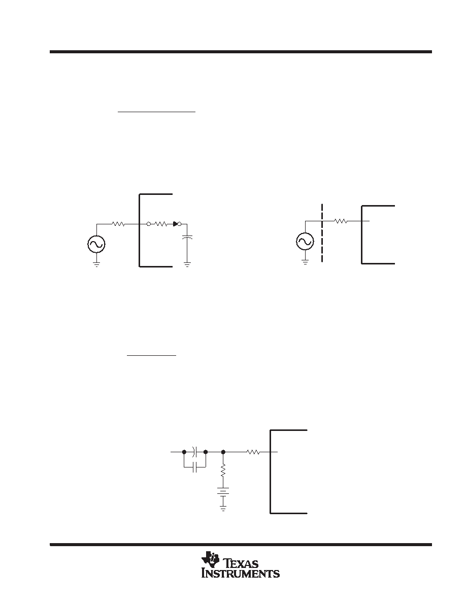
Figure 12. TLC876 Simplified Equivalent Input
RS
AIN
VS
S1
RSW
Driving
Source
TLC876
CE
RS ≤ 200
AIN
VS
Figure 13. Sample TLC876 Drive Requirements
TLC876
Ideal Source
For many applications, particularly in single supply operation, ac coupling offers a convenient way of biasing
the analog input signal at the proper signal range. Figure 14 shows a typical configuration for ac coupling the
analog input signal to the TLC876. Maintaining the outlined specifications requires careful selection of the
component values. The most important concern is the f–3 dB high-pass corner that is a function of R2, and the
parallel combination of C1 and C2. The f–3 dB point can be approximated by equation 2.
f*3dB +
1
2
p
(R2) Ceq
(2)
where Ceq is the parallel combination of C1 and C2. Since C1 is typically a large electrolytic or tantalum
capacitor, the impedance becomes inductive at high frequencies. Adding a small ceramic or polystyrene
capacitor, C2 of approximately 0.01
F, which is not inductive within the frequency range of interest, maintains
a low impedance. If the minimum expected input signal frequency is 20 kHz, and R2 equals 1 k
and R1 equals
50
, the parallel capacitance of C1 and C2 must be a minimum of 0.008 F to avoid attenuating signals close
to 20 kHz.
AIN
VIN
R2
+
–
VBIAS
C1
C2
R1
TLC876
Figure 14. AC-Coupled Inputs
相關PDF資料 |
PDF描述 |
|---|---|
| TLC876MDWR | 1-CH 10-BIT PROPRIETARY METHOD ADC, PARALLEL ACCESS, PDSO28 |
| TLC876MDW | 1-CH 10-BIT PROPRIETARY METHOD ADC, PARALLEL ACCESS, PDSO28 |
| TLE2426MDREP | SPECIALTY ANALOG CIRCUIT, PDSO8 |
| TLE4202B | BRUSH DC MOTOR CONTROLLER, 2.5 A, PZFM7 |
| TLE4203S | BRUSH DC MOTOR CONTROLLER, 6 A, PSFM7 |
相關代理商/技術參數 |
參數描述 |
|---|---|
| TLC876CPWR | 制造商:TI 制造商全稱:Texas Instruments 功能描述:10-BIT 20 MSPS PARALLEL OUTPUT CMOS ANALOG-TO-DIGITAL CONVERTERS |
| TLC876EVM | 制造商:Rochester Electronics LLC 功能描述:- Bulk 制造商:Texas Instruments 功能描述: |
| TLC876I | 制造商:TI 制造商全稱:Texas Instruments 功能描述:10-BIT 20 MSPS PARALLEL OUTPUT CMOS ANALOG-TO-DIGITAL CONVERTERS |
| TLC876IDB | 制造商:TI 制造商全稱:Texas Instruments 功能描述:10-BIT 20 MSPS PARALLEL OUTPUT CMOS ANALOG-TO-DIGITAL CONVERTERS |
| TLC876IDBLE | 制造商:TI 制造商全稱:Texas Instruments 功能描述:10-BIT 20 MSPS PARALLEL OUTPUT CMOS ANALOG-TO-DIGITAL CONVERTERS |
發布緊急采購,3分鐘左右您將得到回復。